


Mikroelektronika d.o.o.
EEPROM 6 Click Board™
EEPROM 6 Click Board™
SKU: MIKROE-4296
Couldn't load pickup availability


Overview
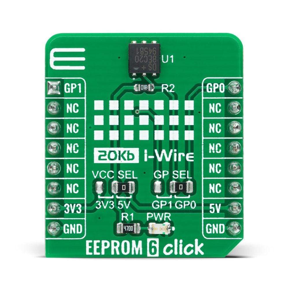
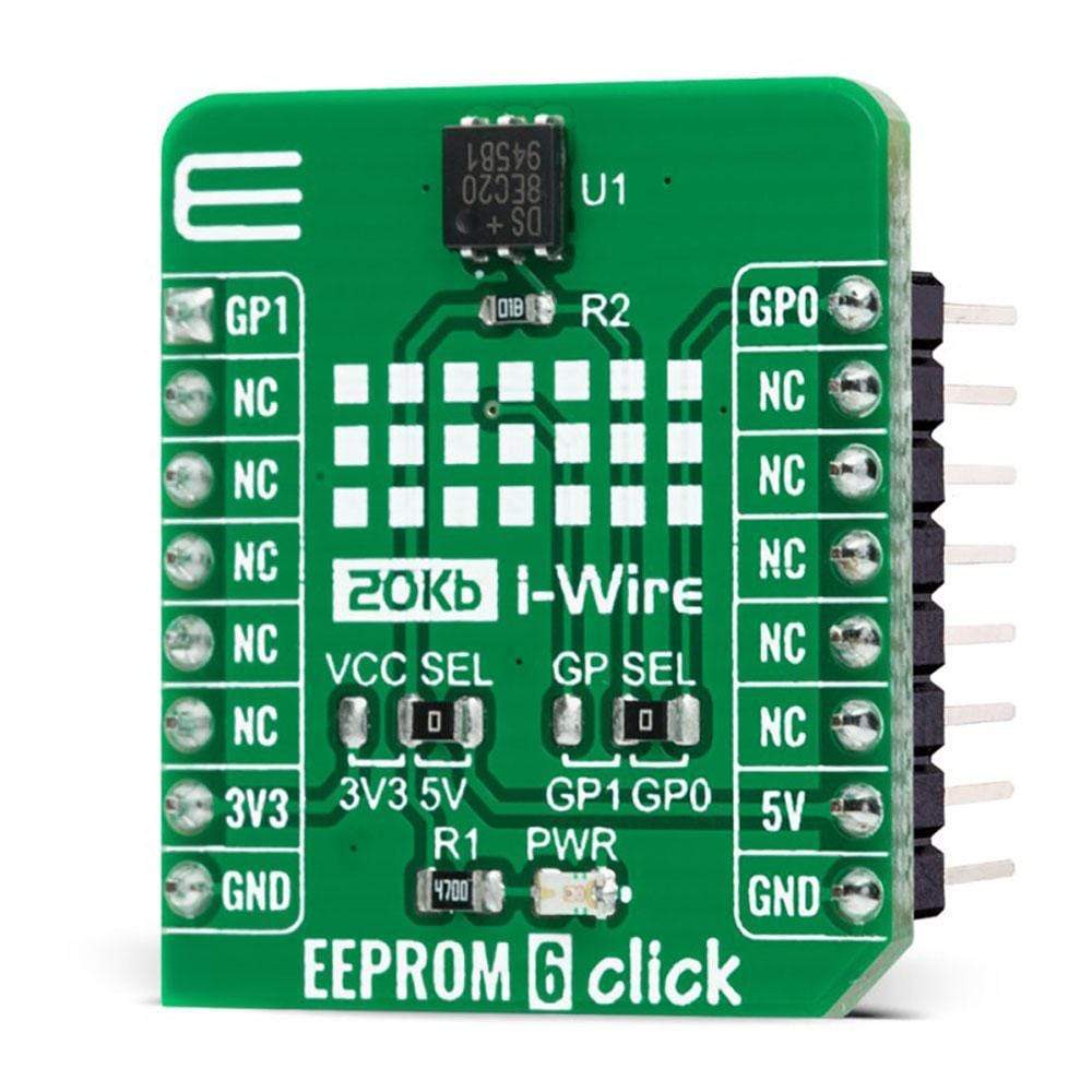
The EEPROM 6 Click Board™ is a compact add-on board that contains a serial EEPROM memory that operates from the 1-Wire interface. This board features the DS28EC20, a 20480-bit EEPROM organized as 80 memory pages of 256 bits each from Maxim Integrated. As a specific feature, blocks of eight memory pages can be write-protected or put in the “EPROM-Emulation” Mode, where bits can only be changed from a 1 to a 0 state. It communicates with MCU at 15.4kbps or 90kbps over the 1-Wire protocol and has a 64-bit registration number that ensures error-free device selection. This Click Board™ is suitable for applications like device authentication, data for self-configuration of central office switches, wireless base stations, or other modular-based rack systems.
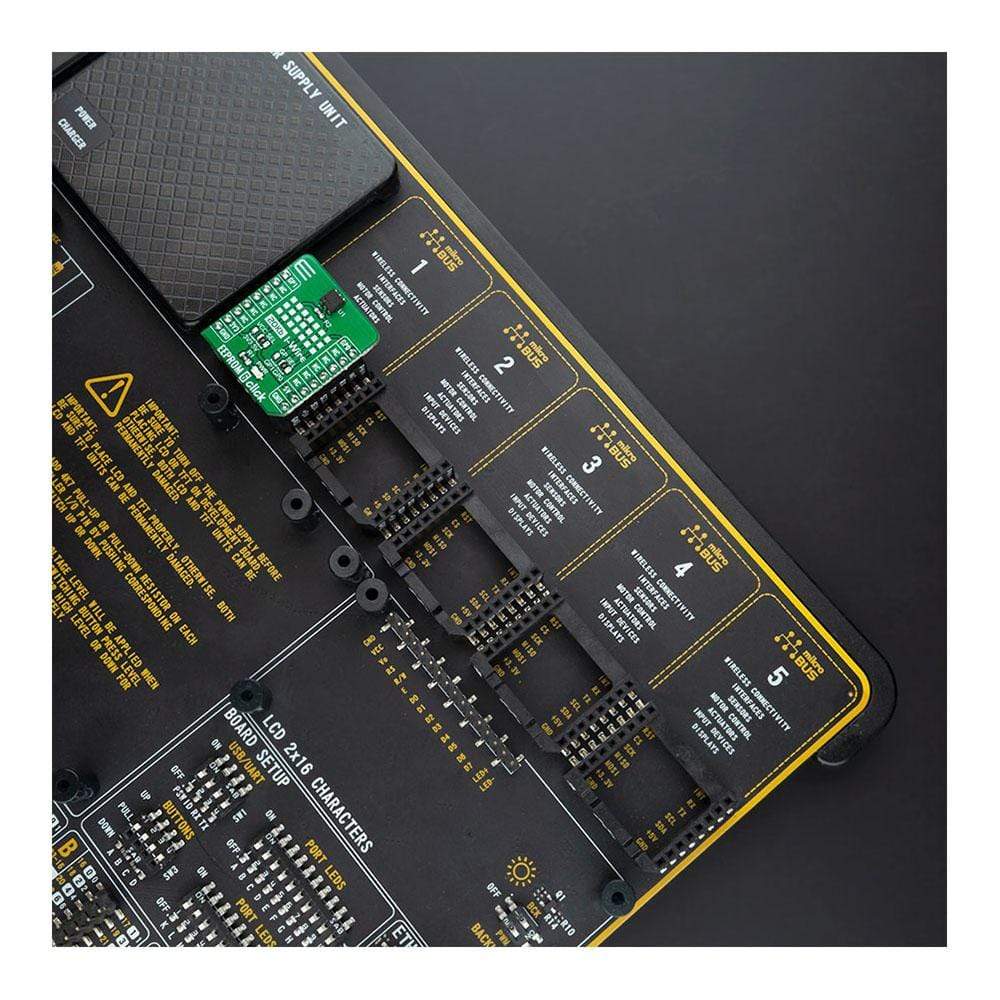
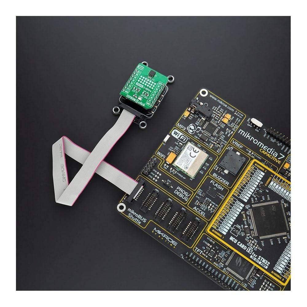
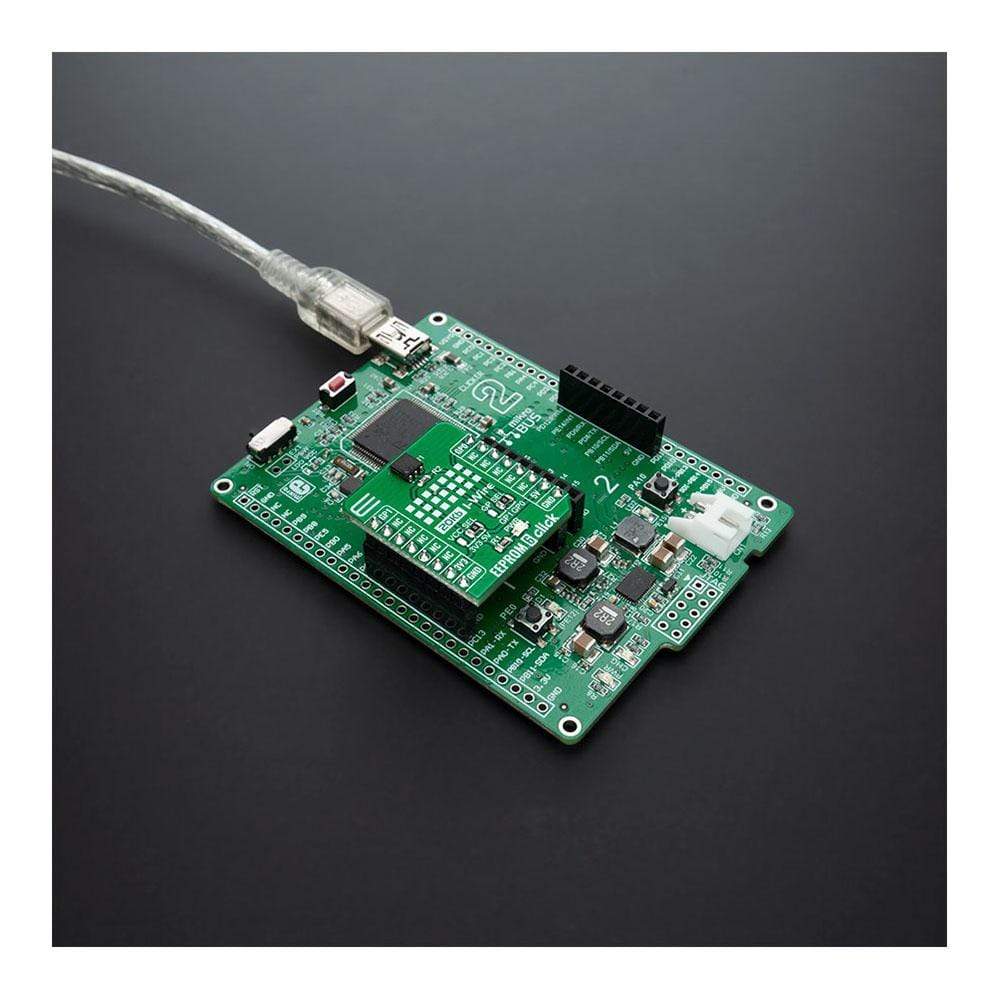
The EEPROM 6 Click Board™ is supported by a mikroSDK compliant library, which includes functions that simplify software development. This Click Board™ comes as a fully tested product, ready to be used on a system equipped with the mikroBUS™ socket.
Downloads
Hoes Does The EEPROM 6 Click Board™ Work?
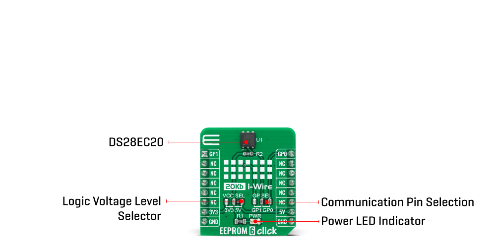
The EEPROM 6 Click Board™ is based on the DS28EC20, a 20Kb of data EEPROM with a fully featured 1-Wire interface in a single chip from Maxim Integrated. The memory is organized as 80 pages of 256 bits each. In addition, the device has one page for control functions such as permanent write protection and EPROM-Emulation mode for individual 2048-bit (8-page) memory blocks. A volatile 256-bit memory page called the scratchpad acts as a buffer when writing data to the EEPROM to ensure data integrity. Data is first written to the scratchpad, from which it can be read back for verification before transferring it to the EEPROM.
Each DS28EC20 has its own unalterable and unique 64-bit registration number. The registration number guarantees unique identification and is used to address the device in a multidrop 1-Wire net environment. In addition to the EEPROM, the device has a 32-byte volatile scratchpad. Writes to the EEPROM array are a two-step process. First, data is written to the scratchpad and then copied into the main array. The user can verify the data in the scratchpad before copying.
The protocol for accessing the DS28EC20 through the 1-Wire interface consists of additional steps:
- Initialization sequence - It consists of a reset pulse transmitted by the MCU followed by the presence pulse transmitted by the DS28EC20, which gives the MCU information that the DS28EC20 is on the bus and is ready to operate.
- ROM Function Command - Once the MCU has detected a presence, it can issue one of the seven ROM function commands that the DS28EC20 support.
- Memory Function Command - Commands necessary for accessing the memory of the DS28EC20.
- Transaction/Data - The idle state for the 1-Wire bus is high. If for any reason a transaction needs to be suspended, the bus MUST be left in the idle state if the transaction is to resume. If this does not occur and the bus is left low for more than 16μs (Overdrive speed) or more than 120μs (Standard speed), one or more devices on the bus can be reset.
The EEPROM 6 Click Board™ communicates with MCU using the 1-Wire interface that supports both a Standard and Overdrive communication speed of 15.4kbps (max) and 90kbps (max), respectively. If not explicitly set into the Overdrive mode, the DS28EC20 communicates at Standard speed. The 1-Wire communication line is routed to the SMD jumper labeled as GP SEL, which allows routing of the 1-Wire communication either to the PWM pin or to the AN pin of the mikroBUS™ socket. These pins are labeled as GP0 and GP1 respectively, the same as the SMD jumper positions, making the selection of the desired pin simple and straightforward.
The EEPROM 6 Click Board™ is designed to be operated with both 3.3V and 5V logic voltage levels that can be selected via VCC SEL jumper. This allows for both 3.3V and 5V capable MCUs to use the 1-Wire communication lines properly. However, the Click board™ comes equipped with a library that contains easy to use functions and an example code that can be used as a reference for further development.
SPECIFICATIONS
| Type | EEPROM |
| Applications | Can be used for applications like device authentication, analog-sensor calibration, ink and toner printer cartridge identification, data for self-configuration of central office switches, wireless base stations, or other modular-based rack systems. |
| On-board modules | The EEPROM 6 Click Board™ is based on the DS28EC20, a 20Kb of data EEPROM with a fully featured 1-Wire interface in a single chip from Maxim Integrated. |
| Key Features | Unique registration number that ensures error-free device selection, switchpoint hysteresis and filtering to optimize performance in the presence of noise, 200k write/erase cycle endurance, and more. |
| Interface | 1-Wire |
| Compatibility | mikroBUS |
| Click board size | S (28.6 x 25.4 mm) |
| Input Voltage | 3.3V or 5V |
PINOUT DIAGRAM
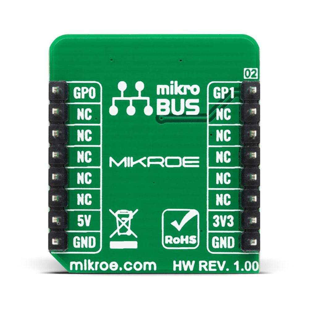
This table shows how the pinout on EEPROM 6 Click Board™ corresponds to the pinout on the mikroBUS™ socket (the latter shown in the two middle columns).
| Notes | Pin | Pin | Notes | ||||
|---|---|---|---|---|---|---|---|
| 1-Wire Data IN/OUT | GP1 | 1 | AN | PWM | 16 | GP0 | 1-Wire Data IN/OUT |
| NC | 2 | RST | INT | 15 | NC | ||
| NC | 3 | CS | RX | 14 | NC | ||
| NC | 4 | SCK | TX | 13 | NC | ||
| NC | 5 | MISO | SCL | 12 | NC | ||
| NC | 6 | MOSI | SDA | 11 | NC | ||
| Power Supply | 3.3V | 7 | 3.3V | 5V | 10 | 5V | Power Supply |
| Ground | GND | 8 | GND | GND | 9 | GND | Ground |
ONBOARD SETTINGS AND INDICATORS
| Label | Name | Default | Description |
|---|---|---|---|
| LD1 | PWR | - | Power LED Indicator |
| JP1 | VCC SEL | Right | Power Supply Voltage Selection 3V3/5V: Left position 3V3, Right position 5V |
| JP2 | GP SEL | Right | 1-Wire Data Communication Pin Selection: Left position GP1, Right position GP0 |
EEPROM 6 CLICK ELECTRICAL SPECIFICATIONS
| Description | Min | Typ | Max | Unit |
|---|---|---|---|---|
| Supply Voltage | -0.5 | - | 6 | V |
| Memory Size | - | - | 20 | Kb |
| Write/Erase Cycles (Endurance) | 200k | - | - | cycle |
| Operating Temperature Range | -40 | - | +85 | °C |
| General Information | |
|---|---|
Part Number (SKU) |
MIKROE-4296
|
Manufacturer |
|
| Physical and Mechanical | |
Weight |
0.018 kg
|
| Other | |
EAN |
8606027380747
|
Frequently Asked Questions
Have a Question?
Be the first to ask a question about this.