Oximeter 2 Click Board
Overview
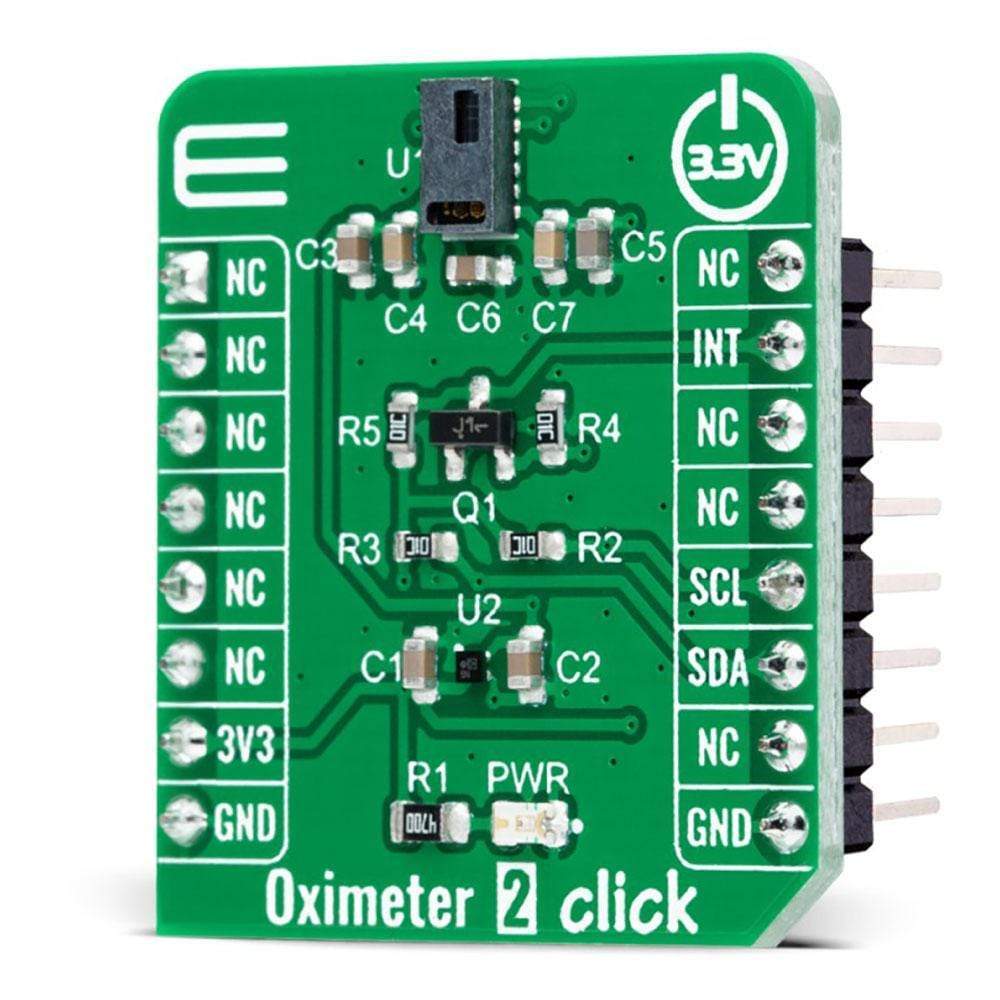
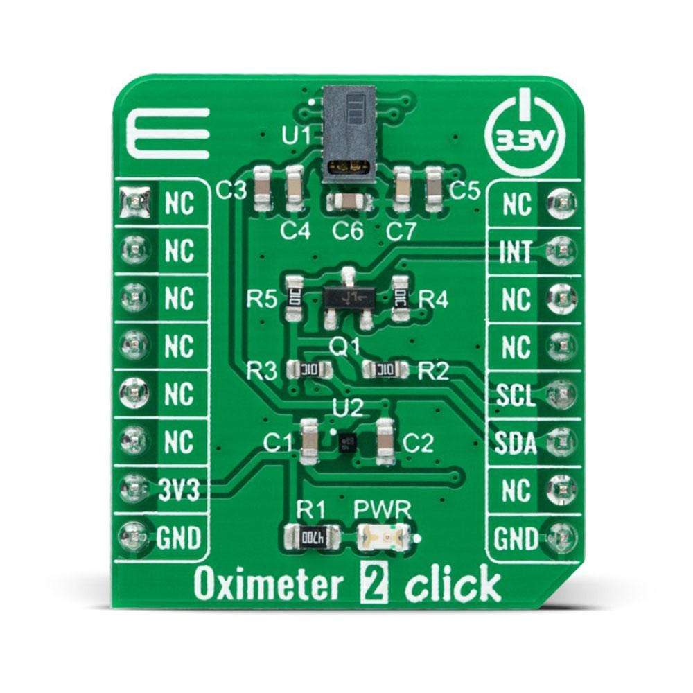
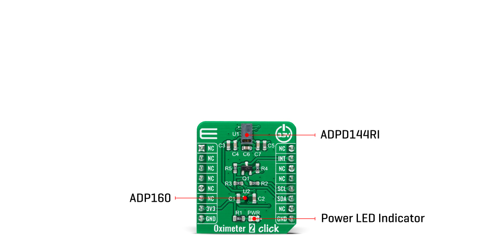
The Oximeter 2 Click Board™ is a compact add-on board suitable for measuring blood oxygen saturation. This board features the ADPD144RI, a PPG optical sensor for photoplethysmography detection of blood oxygenation from Analog Devices. It combines LED emitters and sensitive 4-channel photodiodes with a custom ASIC that provides optical isolation between the integrated LED emitters and the detection photodiodes to improve the signal-to-noise ratio (SNR). PPG detection of blood oxygenation is achieved by synchronous detection in red and infrared wavelengths. Synchronous measurement allows rejection of both DC and AC ambient light interference with low power consumption. This Click Board™ makes it an excellent choice for applications such as optical pulse oximetry and health monitoring.
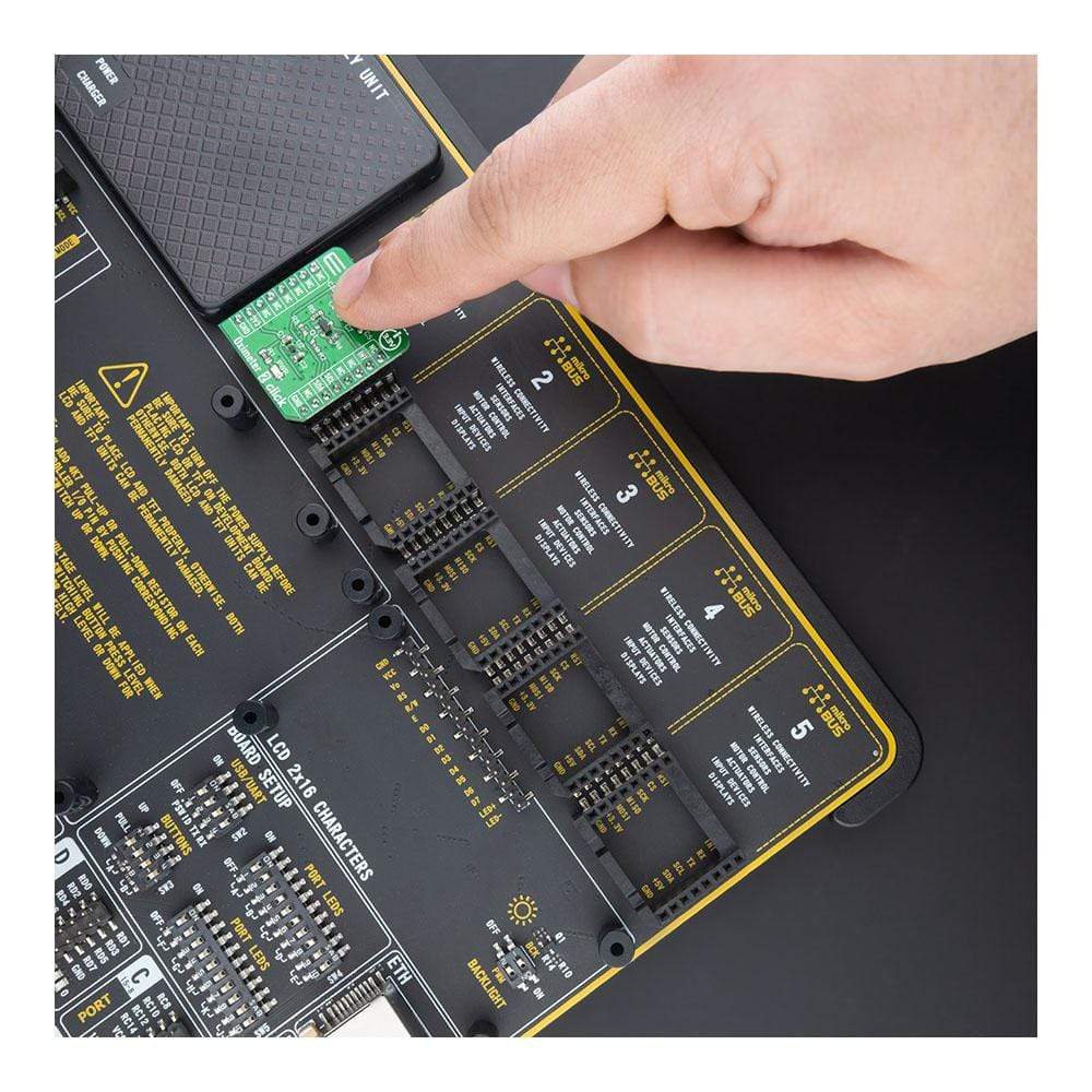
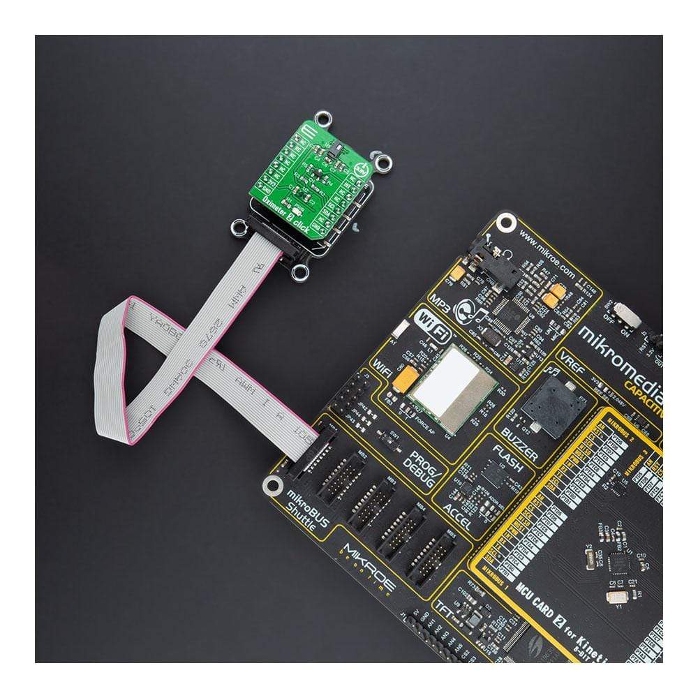
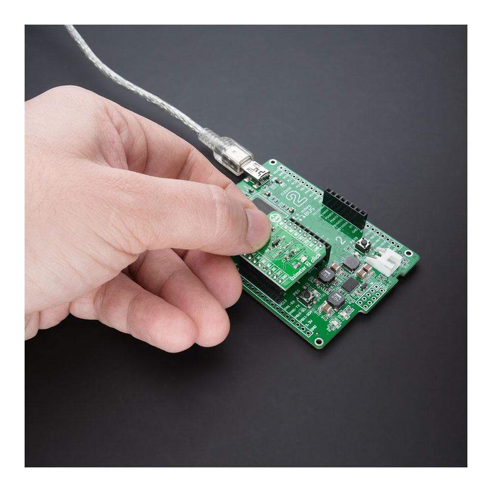
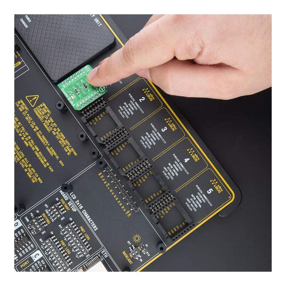
The Oximeter 2 Click Board™ is supported by a mikroSDK compliant library, which includes functions that simplify software development. This Click Board™ comes as a fully tested product, ready to be used on a system equipped with the mikroBUS™ socket.
How Does The Oximeter 2 Click Board™ Work?
The Oximeter 2 Click Board™ is based on the ADPD144RI, a highly integrated, photometric front end optimized for photoplethysmography (PPG) detection of blood oxygenation from Analog Devices. It combines highly efficient, red and infrared LED emitters, with 660nm red and 880nm IR wavelengths, and a sensitive 4-channel photodiode with a custom ASIC that provides optical isolation between the integrated LED emitters and the detection photodiodes to improve the signal-to-noise ratio. It uses synchronous detection of optical pulses to enhance the rejection of ambient light in addition to low power consumption.
The Oximeter 2 Click Board™ is designed for ultralow direct optical reflections, with independent AFE settings per channel and I2C control interface. The integrated LED emitters produce light pulses synchronous with the active sampling period of the AFE, which consisting of a programmable TIA, a band-pass filter, and an integrator. The processed analog signals are digitized by a 14-bit ADC and summed by the 20-bit burst accumulator. Four simultaneous sampling channels are matrixed into two independent time slots (one for each LED wavelength). An adjustable number of pulses per sample, accumulation, and averaging can be applied to multiple samples to increase the dynamic range to 27 bits.
The Oximeter 2 Click Board™ communicates with MCU using the standard I2C 2-Wire interface, with a typical clock frequency of 400kHz. A high-speed I2C interface allows data to be read from output registers directly or through a FIFO buffer. All register writes are single word only and require 16 bits of data. It also comes with a programmable interrupt line, labelled as INT and routed on the INT pin of the mikroBUS™ socket that simplifies timely data access. The ADPD144RI does not require a specific Power-Up sequence but requires a supply voltage of 1.8V in order to work properly. Therefore, a small regulating LDO is used, the ADP160 from Analog Devices, providing a 1.8V out of 3.3V mikroBUS™ rail.
The Oximeter 2 Click Board™ is designed to be operated only with a 3.3V logic voltage level. A proper logic voltage level conversion should be performed before the Click board™ is used with MCUs with different logic levels. However, MikroE equipped its users with a library that contains functions and an example code that can be used, as a reference, for further development.
SPECIFICATIONS
Type | Biometrics |
Applications | Can be used for applications such as optical pulse oximetry and health monitoring. |
On-board modules | ADPD144RI - highly integrated photometric front end optimized for photoplethysmography (PPG) detection of blood oxygenation from Analog Devices ADP160 - ultralow quiescent current linear regulator from Analog Devices |
Key Features | Integrated optical components, fully integrated AFE, ADC, LED drivers, and timing core, low power consumption, designed for ultralow direct optical reflections, and more. |
Interface | I2C |
Compatibility | mikroBUS |
Click board size | S (28.6 x 25.4 mm) |
Input Voltage | 3.3V |
PINOUT DIAGRAM
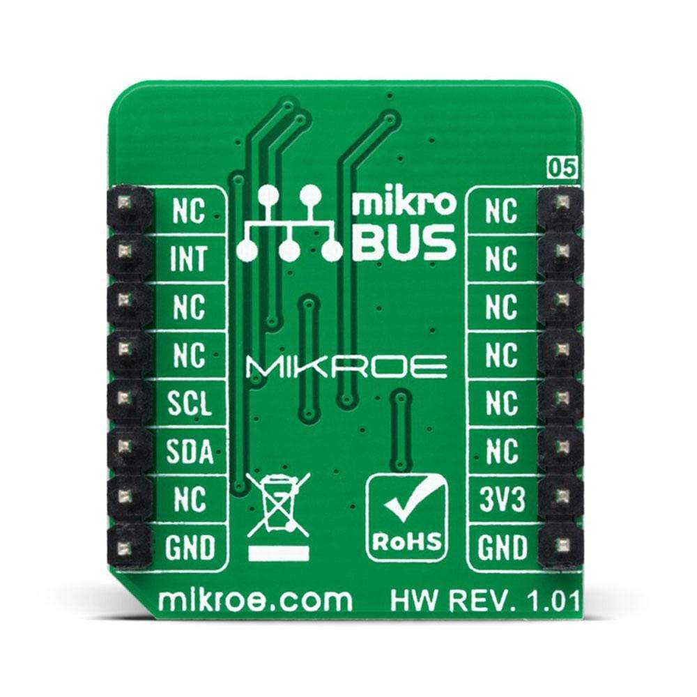
This table shows how the pinout of the Oximeter 2 Click Board™ corresponds to the pinout on the mikroBUS™ socket (the latter shown in the two middle columns).
Notes | Pin | Pin | Notes | ||||
---|---|---|---|---|---|---|---|
NC | 1 | AN | PWM | 16 | NC | ||
NC | 2 | RST | INT | 15 | INT | Interrupt | |
NC | 3 | CS | RX | 14 | NC | ||
NC | 4 | SCK | TX | 13 | NC | ||
NC | 5 | MISO | SCL | 12 | SCL | I2C Clock | |
NC | 6 | MOSI | SDA | 11 | SDA | I2C Data | |
Power Supply | 3.3V | 7 | 3.3V | 5V | 10 | NC | |
Ground | GND | 8 | GND | GND | 9 | GND | Ground |
ONBOARD SETTINGS AND INDICATORS
Label | Name | Default | Description |
---|---|---|---|
LD1 | PWR | - | Power LED Indicator |
OXIMETER 2 CLICK ELECTRICAL SPECIFICATIONS
Description | Min | Typ | Max | Unit |
---|---|---|---|---|
Supply Voltage | - | 3.3 | - | V |
Red LED Wavelenght | - | 660 | - | nm |
Infrared LED Wavelenght | - | 880 | - | nm |
ADC Resolution | - | 14 | - | bits |
Operating Temperature Range | -40 | +25 | +85 | °C |
Software Support
We provide a library for the Oximeter 2 Click Board™ as well as a demo application (example), developed using MikroElektronika compilers. The demo can run on all the main MikroElektronika development boards.
The package can be downloaded/installed directly form compilers IDE(recommended way), or downloaded from our LibStock, or found on mikroE Github account.
Library Description
This library contains API for the Oximeter 2 Click Board™ driver.
Key Functions
void oximeter2_cfg_setup ( oximeter2_cfg_t *cfg );
- Config Object Initialization function.OXIMETER2_RETVAL oximeter2_init ( oximeter2_t *ctx, oximeter2_cfg_t *cfg );
- Initialization function.
Example Description
This application collects data from the sensor, calculates it and then logs the result.
The demo application is composed of two sections :
void oximeter2_write_res ( uint32_t data_write ) { log_printf( &logger, "%urn", data_write ); } void oximeter2_logs_results( void ) { uint8_t final_result; oximeter2_read_data( &oximeter2, &res_slot[ 0 ] ); log_printf( &logger, "Average result per photodiode is: rn" ); switch ( oximeter2.enabled_channel ) { case OXIMETER2_CH3_CH4_SELECTED: { log_printf( &logger, "PD3: " ); oximeter2_write_res( res_slot[ 2 ] ); log_printf( &logger, "PD4: " ); oximeter2_write_res( res_slot[ 3 ] ); final_result = ( res_slot[ 2 ] + res_slot[ 3 ] ) / 1000; break; } case OXIMETER2_ALL_CHANNELS_SELECTED: { log_printf( &logger, "PD1: " ); oximeter2_write_res( res_slot[ 0 ] ); log_printf( &logger, "PD2: " ); oximeter2_write_res( res_slot[ 1 ] ); log_printf( &logger, "PD3: " ); oximeter2_write_res( res_slot[ 2 ] ); log_printf( &logger, "PD4: " ); oximeter2_write_res( res_slot[ 3 ]); final_result = ( res_slot[ 0 ] + res_slot [ 1 ] + res_slot[ 2 ] + res_slot[ 3 ] ) / 1000; break; } default: { break; } } if (final_result > 100) { final_result = 100; } log_printf( &logger, "Average result, in percentage: %urn", ( uint16_t )final_result ); log_printf( &logger, "-------------------------rn" ); Delay_ms( 300 ); } void application_task ( void ) { oximeter2_logs_results(); }
The full application code, and ready to use projects can be installed directly form compilers IDE(recommended) or found on LibStock page or mikroE GitHub account.
Other mikroE Libraries used in the example:
- MikroSDK.Board
- MikroSDK.Log
- Click.Oximeter2
Additional Notes and Information
Depending on the development board you are using, you may need USB UART Click Board™, USB UART 2 Click Board™ or RS232 Click Board™ to connect to your PC, for development systems with no UART to USB interface available on the board. The terminal available in all MikroElektronika compilers, or any other terminal application of your choice, can be used to read the message.
MIKROSDK
The Oximeter 2 Click Board™ is supported with mikroSDK - MikroElektronika Software Development Kit. To ensure proper operation of mikroSDK compliant Click board™ demo applications, mikroSDK should be downloaded from the LibStock and installed for the compiler you are using.
Frequently Asked Questions
Have a Question?
Be the first to ask a question about this.