


Mikroelektronika d.o.o.
H-Bridge 7 Click Board™
H-Bridge 7 Click Board™
SKU: MIKROE-4143
Couldn't load pickup availability
Overview
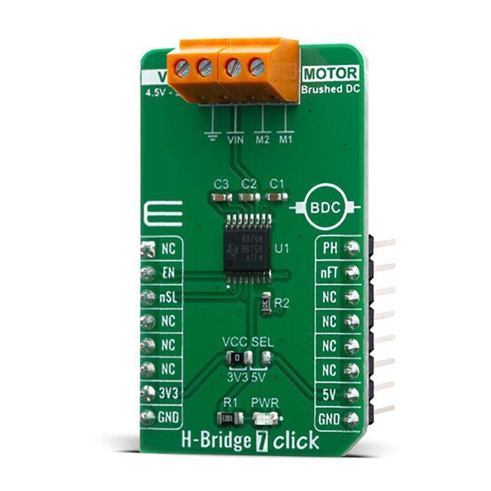
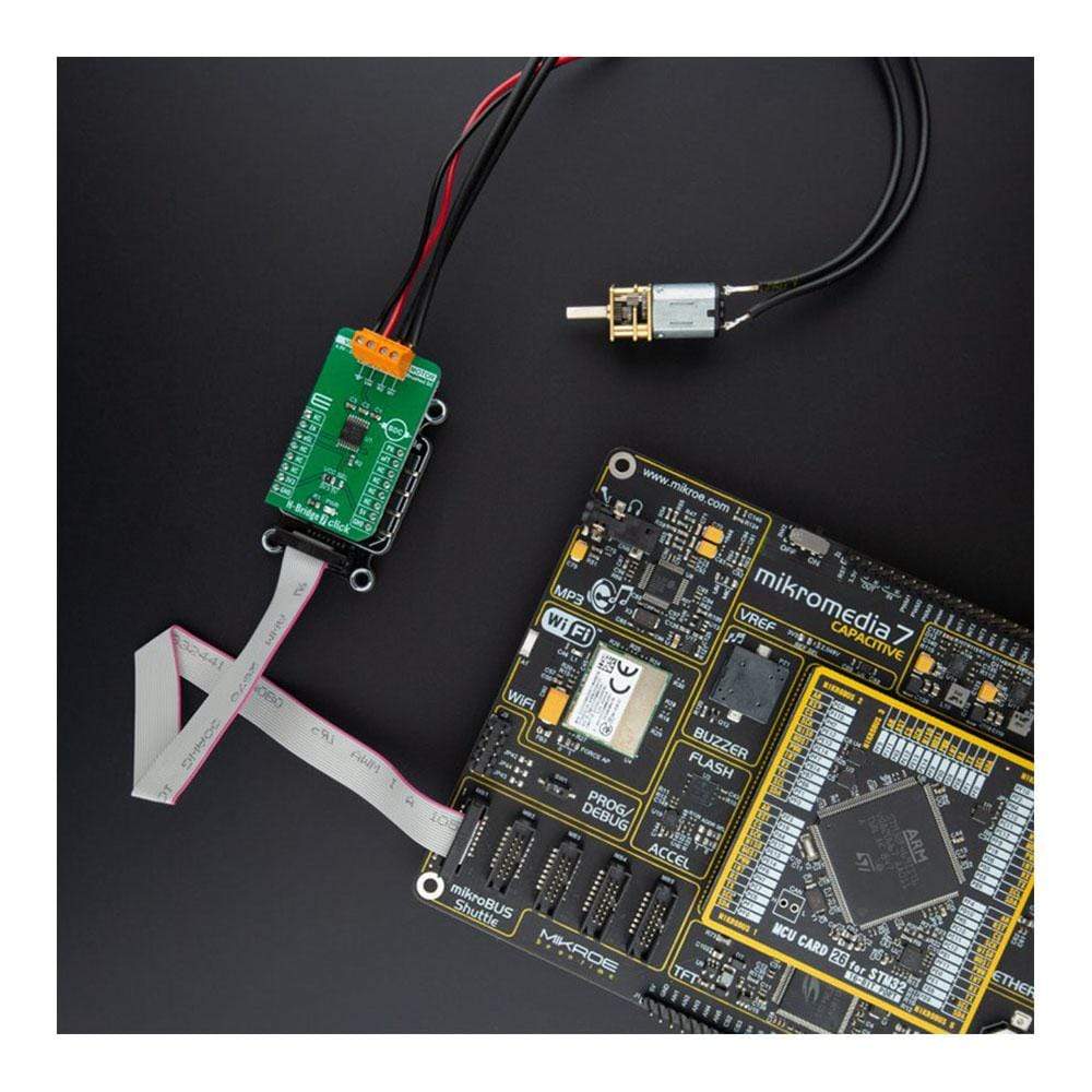
The H-Bridge 7 Click Board™ features flexible motor driver IC for a wide variety of applications, labelled as the DRV8876N. This Click Board™ integrates an N-channel H-bridge, charge pump regulator, and protection circuitry. The charge pump improves efficiency by allowing for both high-side and low-side N-channels MOSFETs and 100% duty cycle support.
This IC allows the H-Bridge 7 Click Board™ to achieve ultra-low quiescent current draw by shutting down most of the internal circuitry with his low-power sleep mode. Internal protection features are provided for supply under-voltage lockout (UVLO), charge pump under-voltage (CPUV), output overcurrent (OCP), and device overtemperature (TSD). Fault conditions are indicated on the nFAULT pin (nFT pin on mikroBUS™). H-Bridge 7 Click Board™ can be used for DC Brush motor drive, servo motors, actuators, and more.
Downloads
How Does The H-Bridge 7 Click Board™ Work?
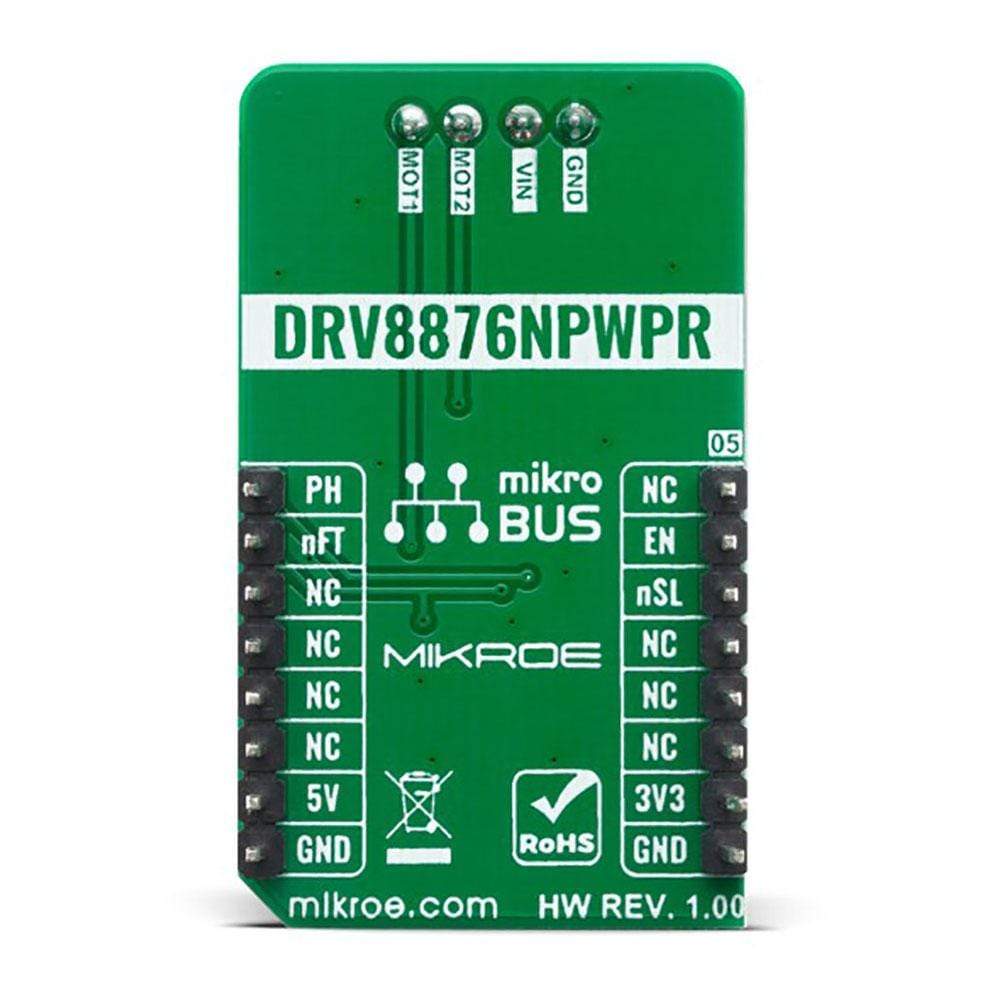
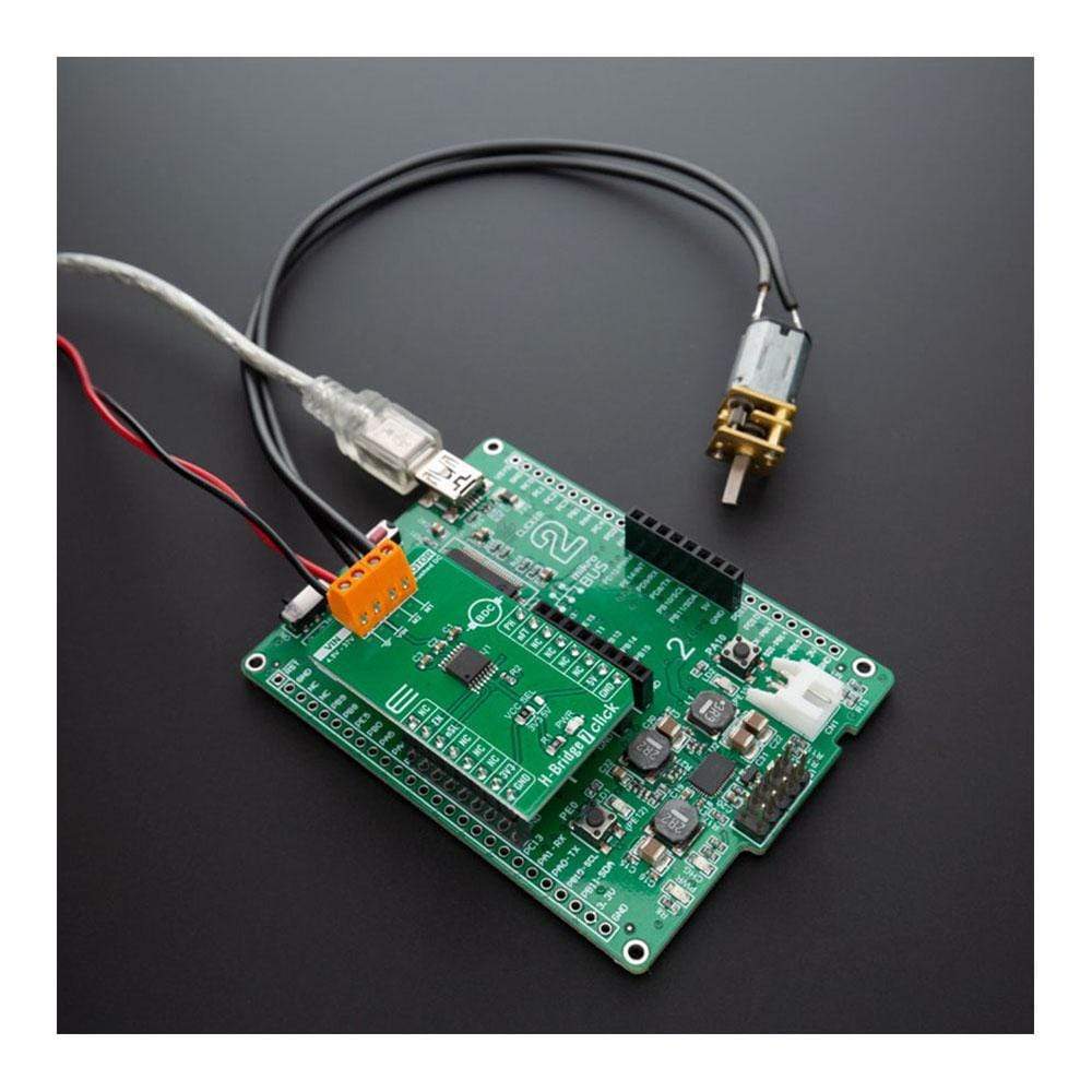
The H-Bridge 7 Click Board™ uses the DRV8876N IC, N-channel H-bridge motor driver from Texas Instruments, that operates from a supply voltage of 4.5V to 37V supporting a wide range of output load currents for various types of motors and loads. This device integrates an H-bridge output power stage that can be operated in control modes that is set by the PMODE pin setting. The device also integrates a charge pump regulator to support more efficient high-side N-channel MOSFETs and 100% duty cycle operation. The device operates from a single power supply input (VM) which can be directly connected to a battery or DC voltage supply. The nSLEEP pin (nSL pin on the mikroBUS™) provides an ultra-low power mode to minimize current draw during system inactivity. Also, this device is fully protected against supply undervoltage, charge pump undervoltage, output overcurrent, and device overtemperature events.
The H-Bridge 7 Click Board™ support different control schemes with the EN/IN1 and PH/IN2 pins. The control mode is selected through the PMODE pin with either logic low, logic high, or setting the pin Hi-Z (in this case PMODE is on the logic low level which means that the device is latched into PH/EN mode). PH/EN mode allows for the H-bridge to be controlled with a speed and direction type of interface.
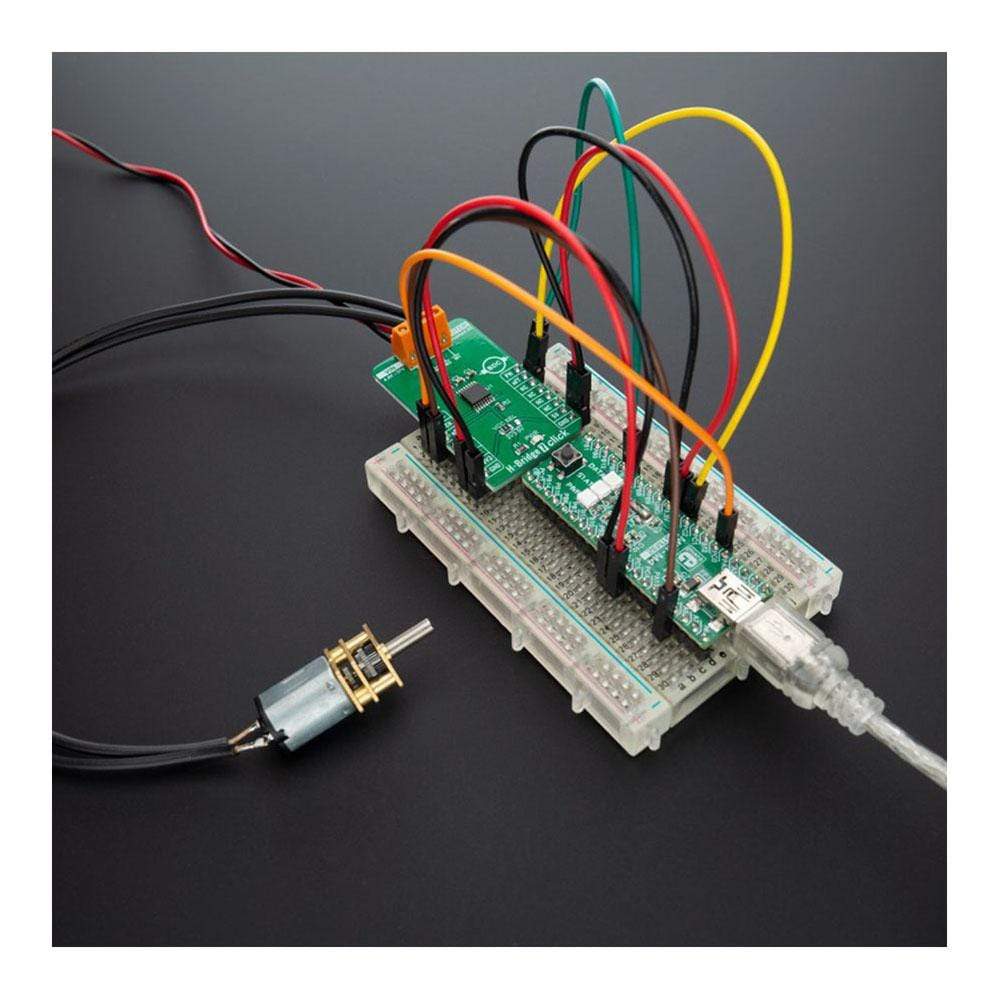
In this configuration, Click board™ drives a bidirectional current through an external load (such as a brushed DC motor), and the H-bridge polarity and duty cycle are controlled with a PWM and IO resource from the external controller to the EN/IN1 and PH/IN2 pins. The device is then configured for the PH/EN control mode by tying the PMODE pin to GND. Some applications of DRV8876N includes brushed DC motors, solenoids, and actuators, but also can be utilized to drive many common passive loads such as LEDs, resistive elements, relays, etc.
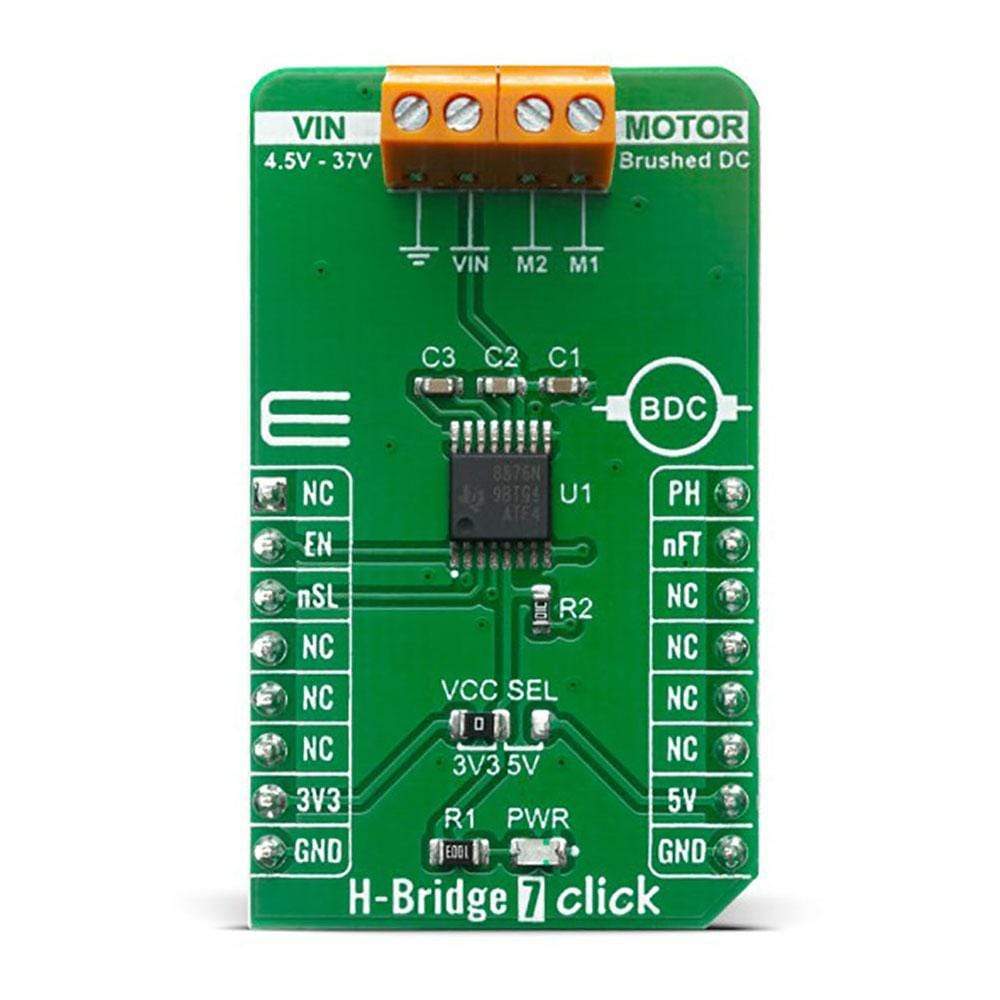
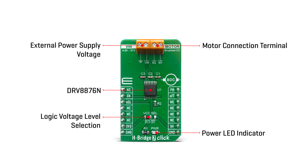
An onboard SMD jumper, labelled as VCC SEL is used to set the voltage levels for the EN/IN1, PH/IN2, nFAULT, and nSLEEP pins of the DRV8876N. It allows for both 3.3V and 5V MCUs to be interfaced with the H-Bridge 7 Click Board™. More information about the DRV8876N can be found in the attached datasheet. However, this Click board™ comes equipped with a library that contains easy to use functions and a usage example that may be used as a reference for the development.
Specifications
| Type | Brushed |
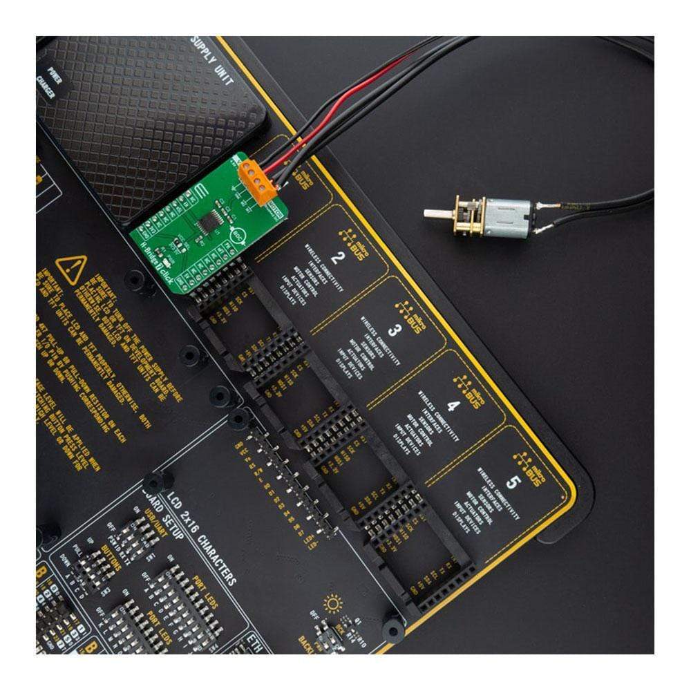
| Applications | Can be used for DC Brush motor drive, servo motors, actuators, and more. |
| On-board modules | H-Bridge 7 Click uses the DRV8876N IC, N-channel H-bridge motor driver from Texas Instruments, that operates from a supply voltage of 4.5V to 37V supporting a wide range of output load currents for various types of motors and loads. |
| Key Features | N-channel H-bridge, charge pump regulator, protection circuitry, Undervoltage lockout, charge pump Undervoltage, output overcurrent, device overtemperature protection |
| Interface | GPIO |
| Compatibility | mikroBUS |
| Click board size | M (42.9 x 25.4 mm) |
| Input Voltage | 3.3V or 5V |
Pinout diagram
This table shows how the pinout on H-Bridge 7 Click corresponds to the pinout on the mikroBUS™ socket (the latter shown in the two middle columns).
| Notes | Pin | Pin | Notes | ||||
|---|---|---|---|---|---|---|---|
| NC | 1 | AN | PWM | 16 | PH | H-bridge control 2 | |
| H-bridge control 1 | EN | 2 | RST | INT | 15 | nFT | Fault indicator |
| Sleep mode | nSL | 3 | CS | RX | 14 | NC | |
| NC | 4 | SCK | TX | 13 | NC | ||
| NC | 5 | MISO | SCL | 12 | NC | ||
| NC | 6 | MOSI | SDA | 11 | NC | ||
| Power Supply | 3.3V | 7 | 3.3V | 5V | 10 | 5V | Power Supply |
| Ground | GND | 8 | GND | GND | 9 | GND | Ground |
Onboard settings and indicators
| Label | Name | Default | Description |
|---|---|---|---|
| LD1 | PWR | - | Power LED Indicator |
| JP1 | VCC SEL | Left | Logic Voltage Level Selection 3V3/5: Left position 3V3, Right position 5V |
| TB1 | POWER | - | 4.5V to 37V Power Supply Input |
| TB2 | MOTOR | - | H-bridge Output |
Maximum Ratings (Limiting Conditions)
| Description | Min | Typ | Max | Unit |
|---|---|---|---|---|
| Supply Voltage (VM) | -0.3 | - | +40 | V |
| Logic Pin Voltage (GPIO) | -0.3 | - | 5.75 | V |
| Maximum Output Current | 0 | - | 3.5 | A |
| Operating Temperature Range | -40 | - | +125 | °C |
| General Information | |
|---|---|
Part Number (SKU) |
MIKROE-4143
|
Manufacturer |
|
| Physical and Mechanical | |
Weight |
0.02 kg
|
| Other | |
EAN |
8606018717699
|
Frequently Asked Questions
Have a Question?
Be the first to ask a question about this.