


Mikroelektronika d.o.o.
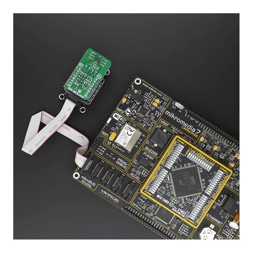
6DOF IMU 3 Click Board™
6DOF IMU 3 Click Board™
SKU: MIKROE-4086
Couldn't load pickup availability
Key Features
Overview
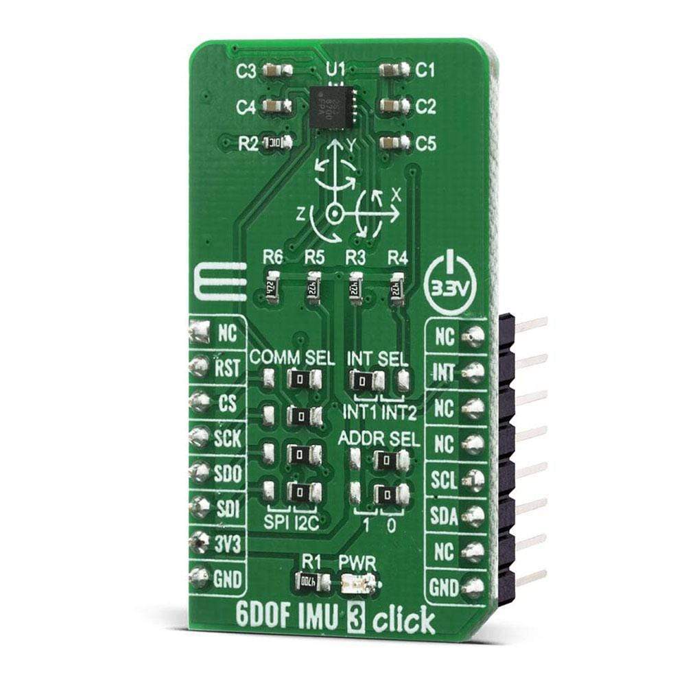
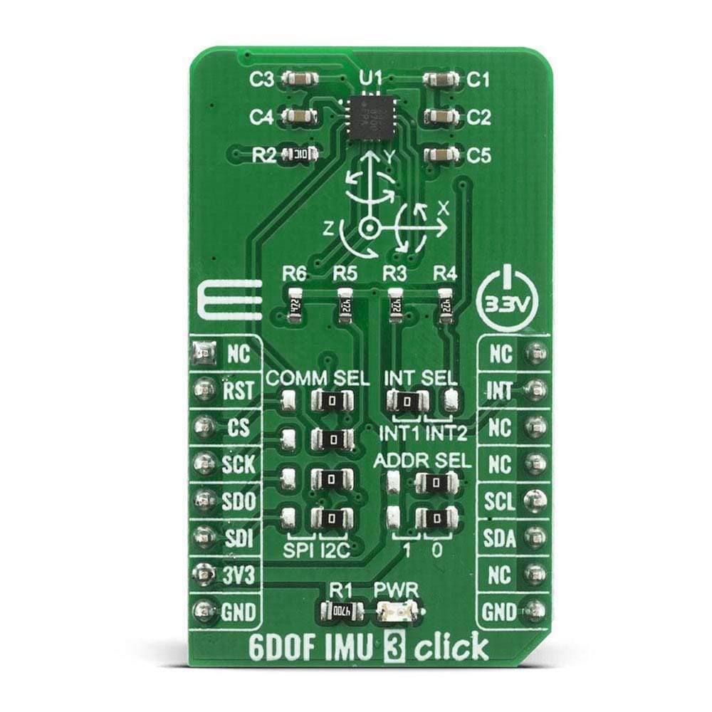
The 6DOF IMU 3 Click Board™ is a complete 6-axis detection development board suitable for movement and position tracking devices. This Click Board™ board features the compact FXOS8700CQ motion sensor from NXP, an integrated 3-axis linear accelerometer and a 3-axis magnetometer combined in one package.
The device supports a selectable I2C or point-to-point SPI serial interface with a 14-bit accelerometer and 16-bit magnetometer which are combined with a high-performance ASIC to enable an eCompass solution capable of a typical orientation resolution of 0.1° and sub-5° compass heading accuracy for many applications.
Downloads
How Does The 6DOF IMU 3 Click Board™ Work?
The 6DOF IMU 3 Click Board™ is based around the FXOS8700CQ, which is a small, low-power, 3-axis, linear accelerometer and 3-axis magnetometer combined into a single package, from NXP. The device features a selectable I2C or point-to-point SPI serial interface with 14-bit accelerometer and 16-bit magnetometer ADC resolution along with smart-embedded functions.The FXOS8700CQ has dynamically selectable acceleration full-scale ranges of ±2 g/±4 g/±8 g and a fixed magnetic measurement range of ±1200 μT. Output data rates (ODR) from 1.563 Hz to 800 Hz are selectable by the user for each sensor. Interleaved magnetic and acceleration data is available at ODR rates of up to 400 Hz.

Sensitivity of the sensor is represented in mg/LSB for the accelerometer and μT/LSB for the magnetometer. The magnetometer sensitivity is fixed at 0.1 μT/LSB. The accelerometer sensitivity changes with the full-scale range selected by the user. Accelerometer sensitivity is 0.244 mg/LSB in 2 g mode, 0.488 mg/LSB in 4 g mode, and 0.976 mg/LSB in 8 g mode, making it ideal for applications such as used for security, like motion detection, door opening, smart home applications, robotics and unmanned aerial vehicles (UAVs) with electronic compass (e-compass) function, in medical purposes, like patient monitoring, fall detection and more.
6DOF IMU 3 Click Board™ supports both SPI and I2C communication interfaces, allowing it to be used with a wide range of different MCUs. The communication interface can be selected by moving SMD jumpers grouped under the COM SEL to an appropriate position (SPI or I2C). The slave I2C address can also be configured by an SMD jumper when the Click Board™ is operated in the I2C mode. An SMD jumpers labelled as ADDR SEL is used to set the least significant bit (LSB) of the I2C address. The I2C interface is compliantwith fast mode (400 kHz), and normal mode (100 kHz) I2C standards, while the SPI interface is a classical master/slave serial port. The FXOS8700CQ is always considered as the slave and thus is never initiating the communication.
This Click Board™ is designed to be operated only with 3.3V logic level. A proper logic voltage level conversion should be performed before the Click Board™ is used with MCUs with logic levels of 5V.
SPECIFICATIONS
| Type | Motion |
| Applications | For security, like motion detection, door opening, smart home applications, robotics, and unmanned aerial vehicles (UAVs) with electronic compass (e-compass) function, medical, like patient monitoring, fall detection, and rehabilitation, augmented reality (AR), gaming, and real-time activity analysis, etc. |
| On-board modules | FXOS8700CQ is a small, low-power, 3-axis, linear accelerometer and 3-axis, magnetometer combined into a single package |
| Key Features | The 14-bit accelerometer and 16-bit magnetometer are combined with a high-performance ASIC to enable an eCompass solution capable of a typical orientation resolution of 0.1° and sub-5° compass heading accuracy |
| Interface | I2C,SPI |
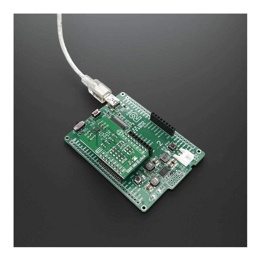
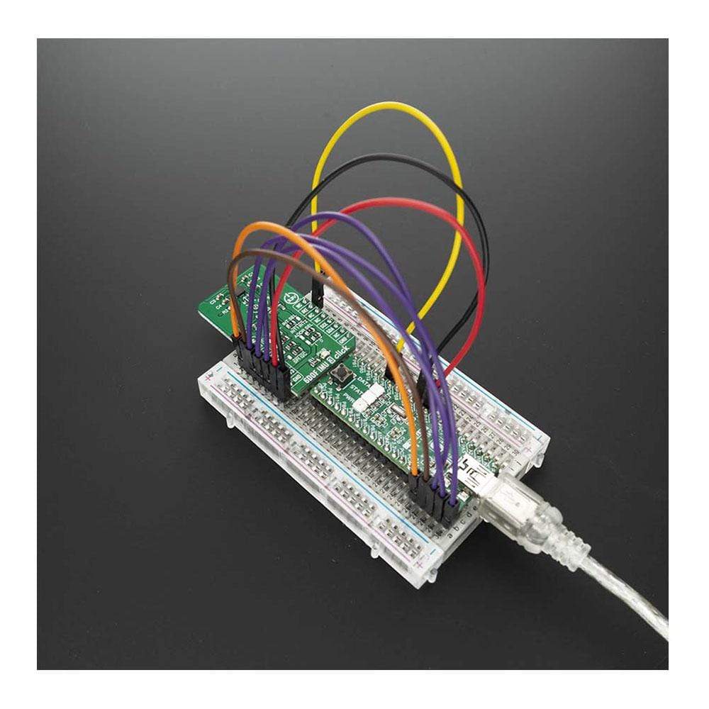
| Compatibility | mikroBUS |
| Click Board™ size | M (42.9 x 25.4 mm) |
| Input Voltage | 3.3V |
PINOUT DIAGRAM
This table shows how the pinout on 6DOF IMU 3 Click Board™ corresponds to the pinout on the mikroBUS socket (the latter shown in the two middle columns).
| Notes | Pin | Pin | Notes | ||||
|---|---|---|---|---|---|---|---|
| NC | 1 | AN | PWM | 16 | NC | ||
| Reset | RST | 2 | RST | INT | 15 | INT | Interrupt |
| SPI Chip Select | CS | 3 | CS | RX | 14 | NC | |
| SPI Clock | SCK | 4 | SCK | TX | 13 | NC | |
| SPI Data OUT | SDO | 5 | MISO | SCL | 12 | SCL | I2C Clock |
| SPI Data IN | SDI | 6 | MOSI | SDA | 11 | SDA | I2C Data |
| Power Supply | 3.3V | 7 | 3.3V | 5V | 10 | NC | |
| Ground | GND | 8 | GND | GND | 9 | GND | Ground |
ONBOARD SETTINGS AND INDICATORS
| Label | Name | Default | Description |
|---|---|---|---|
| LD1 | PWR | - | Power LED Indicator |
| JP1 | INT SEL | Left | Interrupt pin selection, left position INT1, right position INT2 |
| JP2 | ADDR SEL | Right | I2C adress selection pin SA0, left position 3V3 (H), right position 0V (L) |
| JP3 | ADDR SEL | Right | I2C adress selection pin SA1, left position 3V3 (H), right position 0V (L) |
| JP4 | COMM SEL | Right | Communication selection, left position SPI CS pin, right position I2C SA1 pin |
| JP5 | COMM SEL | Right | Communication selection, left position SPI SCK pin, right position I2C SCL pin |
| JP6 | COMM SEL | Right | Communication selection, left position SPI MISO pin, right position I2C SA0 pin |
| JP7 | COMM SEL | Right | Communication selection, left position SPI MOSI pin, right position I2C SDA pin |
| General Information | |
|---|---|
Part Number (SKU) |
MIKROE-4086
|
Manufacturer |
|
| Physical and Mechanical | |
Weight |
0.017 kg
|
| Other | |
EAN |
8606018717286
|
Frequently Asked Questions
Have a Question?
Be the first to ask a question about this.