


Mikroelektronika d.o.o.
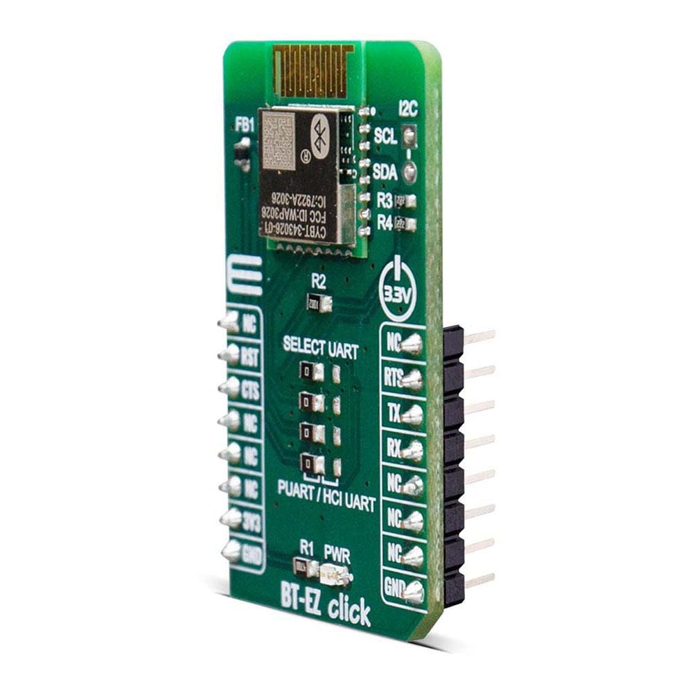
BT-EZ Click Board™
BT-EZ Click Board™
SKU: MIKROE-4038
Couldn't load pickup availability
Overview
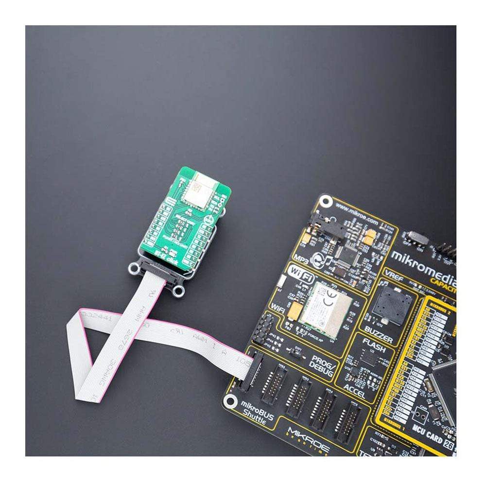
The BT-EZ Click Board™ provides BLE connectivity for any embedded application. BT-EZ Click Board™ based on the CYBT-343026-01 module from Cypress. This Click Board™ is a fully integrated Bluetooth low energy module, mentioned for easy integration into various electronic devices. Given its features, this Click Board™ can be used for health, sports, and wellness devices as well as Industrial, home, and building automation, and smartphone, tablet, and PC accessories.
Downloads
How Does The BT-EZ Click Board™ Work?
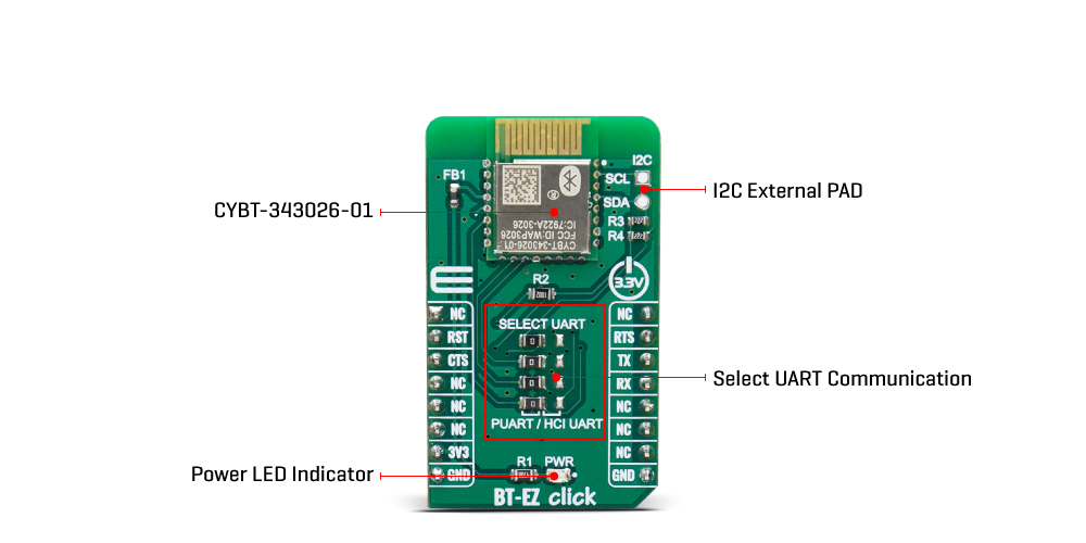
The BT-EZ Click Board™ features the CYBT-343026-01, a module from Cypress that has some impressive features including the fact that it includes a royalty-free bluetooth stack with Bluetooth 5.0 and BLE supported. Besides that, low power mode enables the module to consume as low as 2.69µA in deep sleep mode, which is ideal for portable, wearable and various other battery powered devices and applications.
The BT-EZ Click Board™ is fully integrated Bluetooth smart ready wireless module which includes an onboard crystal oscillator, passive components, flash memory, and the CYW20706 silicon device from Cypress. The CYBT-343026-01 module also includes Cortex-M3 32-bit processor and 512 KB of onboard serial flash memory and is designed for standalone operation, while the integrated power amplifier is used in order to achieve Class I or Class II output power capability. The BT-EZ Click Board™ uses UART communication and GPIO pins for communication with the main MCU.
The BT-EZ Click Board™ supports two UART communication modes. HCI UART intercafe is a standard, 4-wire interface (RX, TX, RTS, and CTS), with adjustable baud rates from 38400 bps to 4 Mbps. During initial boot, UART speeds may be limited to 750 kbps. The baud rate may be selected via a vendor-specific UART HCI command. The UART clock default setting is 24 MHz, and can be configured to run as high as 48 MHz to support up to 4 Mbps. The baud rate of the CYBT-343026-01UART module is controlled by two values: clock divisor (set in the DLBR register) that divides the UART clock by an integer multiple of 16, and the baud rate adjustment (set in the DHBR register) that is used to specify a number of UART clock cycles to stuff in the first or second half of each bit time.
The BT-EZ Click Board™ has a second UART (PUART) mode, that may be used to interface to other eripherals. This peripheral UART is accessed through the optional I/O ports, which can be configured individually and separately for each signal.
The external I2C pad provides a 2-pin master I2C interface, which can be used to retrieve configuration information from an external EEPROM or to communicate with peripherals such as track-ball or touch-pad modules, and motion tracking ICs used in mouse devices. This interface is compatible with I2C slave devices. I2C does not support multimaster capability or flexible wait-state insertion by either master or slave devices.
The BT-EZ Click Board™ is designed to be operated only with 3.3V logic level. A proper logic voltage level conversion should be performed before the Click board™ is used with MCUs with logic levels of 5V.
SPECIFICATIONS
| Type | BT/BLE |
| Applications | Health/Medical Devices, Sports Activity/Fitness Meters, Beacon Applications, Internet of Things (IoT) Sensor Tag, Remote Control, Wearable Smart Devices and Accessories, Smart Energy/Smart Home, Industrial Control |
| On-board modules | CYBT-343026-01 , Bluetooth 5 low energy module from Cypress |
| Key Features | Bluetooth 5 low energy compliant, integrated antenna, Cortex-M3 32-bit processor |
| Interface | UART |
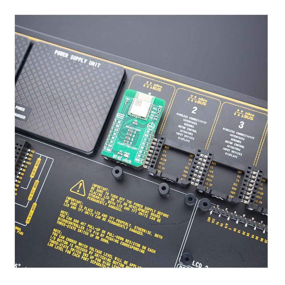
| Compatibility | mikroBUS |
| Click board size | M (42.9 x 25.4 mm) |
| Input Voltage | 3.3V |
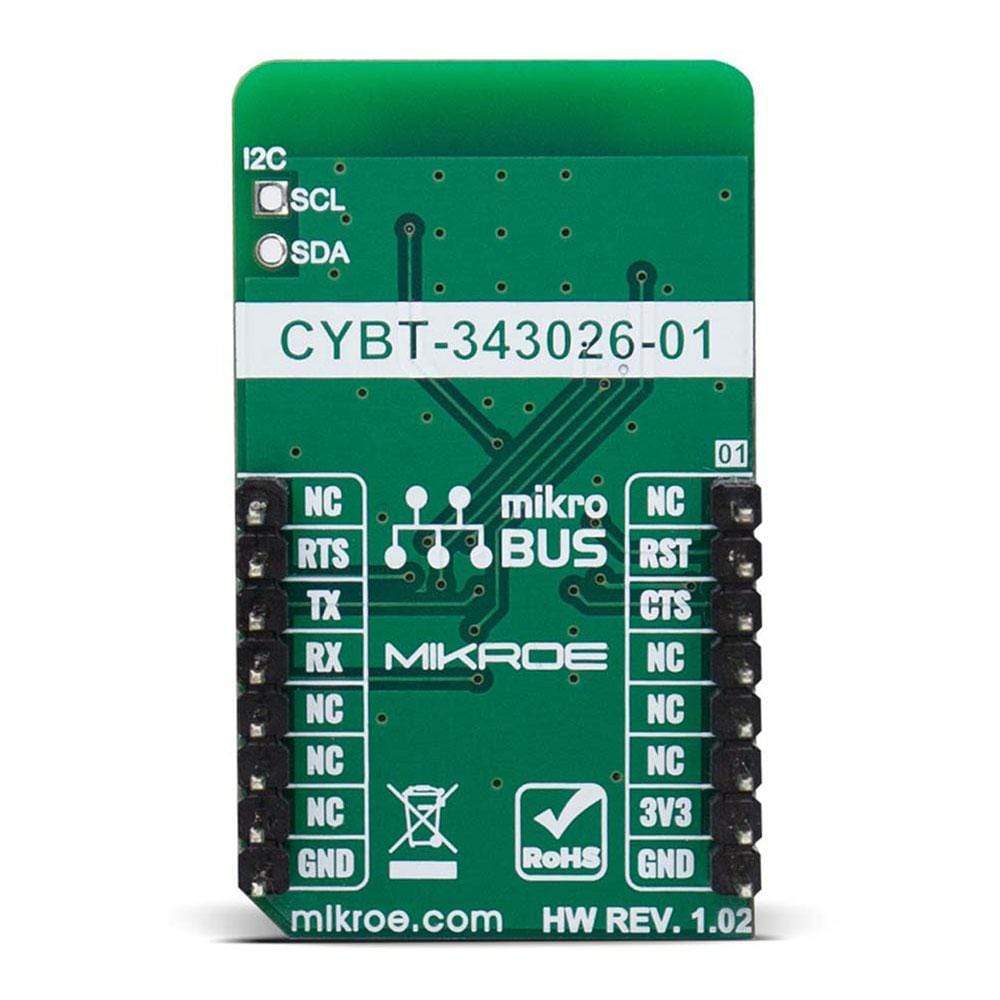
Pinout Diagram
This table shows how the pinout of the BT-EZ Click Board™ corresponds to the pinout on the mikroBUS™ socket (the latter shown in the two middle columns).
| Notes | Pin | Pin | Notes | ||||
|---|---|---|---|---|---|---|---|
| NC | 1 | AN | PWM | 16 | NC | ||
| Reset | RST | 2 | RST | INT | 15 | RTS | UART request to send |
| UART clear to send | CTS | 3 | CS | RX | 14 | TX | UART Transmit |
| NC | 4 | SCK | TX | 13 | RX | UART Receive | |
| NC | 5 | MISO | SCL | 12 | NC | ||
| NC | 6 | MOSI | SDA | 11 | NC | ||
| Power Supply | 3.3V | 7 | 3.3V | 5V | 10 | NC | |
| Ground | GND | 8 | GND | GND | 9 | GND | Ground |
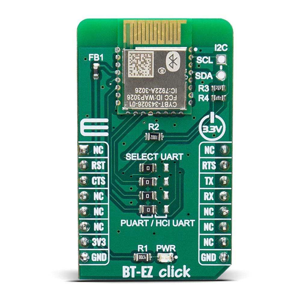
ONBOARD SETTINGS AND INDICATORS
| Label | Name | Default | Description |
|---|---|---|---|
| LD1 | PWR | - | Power LED Indicator |
| J1-J4 | UART SEL | Left | Select UART communication: Left position PUART, right position HCI UART |
| General Information | |
|---|---|
Part Number (SKU) |
MIKROE-4038
|
Manufacturer |
|
| Physical and Mechanical | |
Weight |
0.018 kg
|
| Other | |
EAN |
8606018717965
|
Frequently Asked Questions
Have a Question?
Be the first to ask a question about this.