


Mikroelektronika d.o.o.
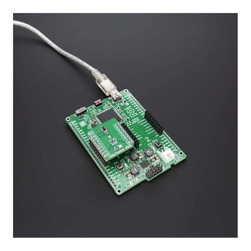
Index Counter Click Board™
Index Counter Click Board™
SKU: MIKROE-4005
Couldn't load pickup availability
Overview
The Index Counter Click Board™ is a simple prototyping high precision Hall-Effect switch solution with direction detection. This board is hosting TLE4966K an integrated circuit dual Hall-effect sensor from Infineon. The sensor is designed specifically for highly accurate applications which use a rotating pole wheel since offers high sensitivity and high stability of the magnetic switching points. Since this sensor is based on two hall probes that provide information about the direction and speed of the moving wheel, this makes this product an excellent choice for applications such as index counting, rotational speed and direction applications, motor-driven position systems.
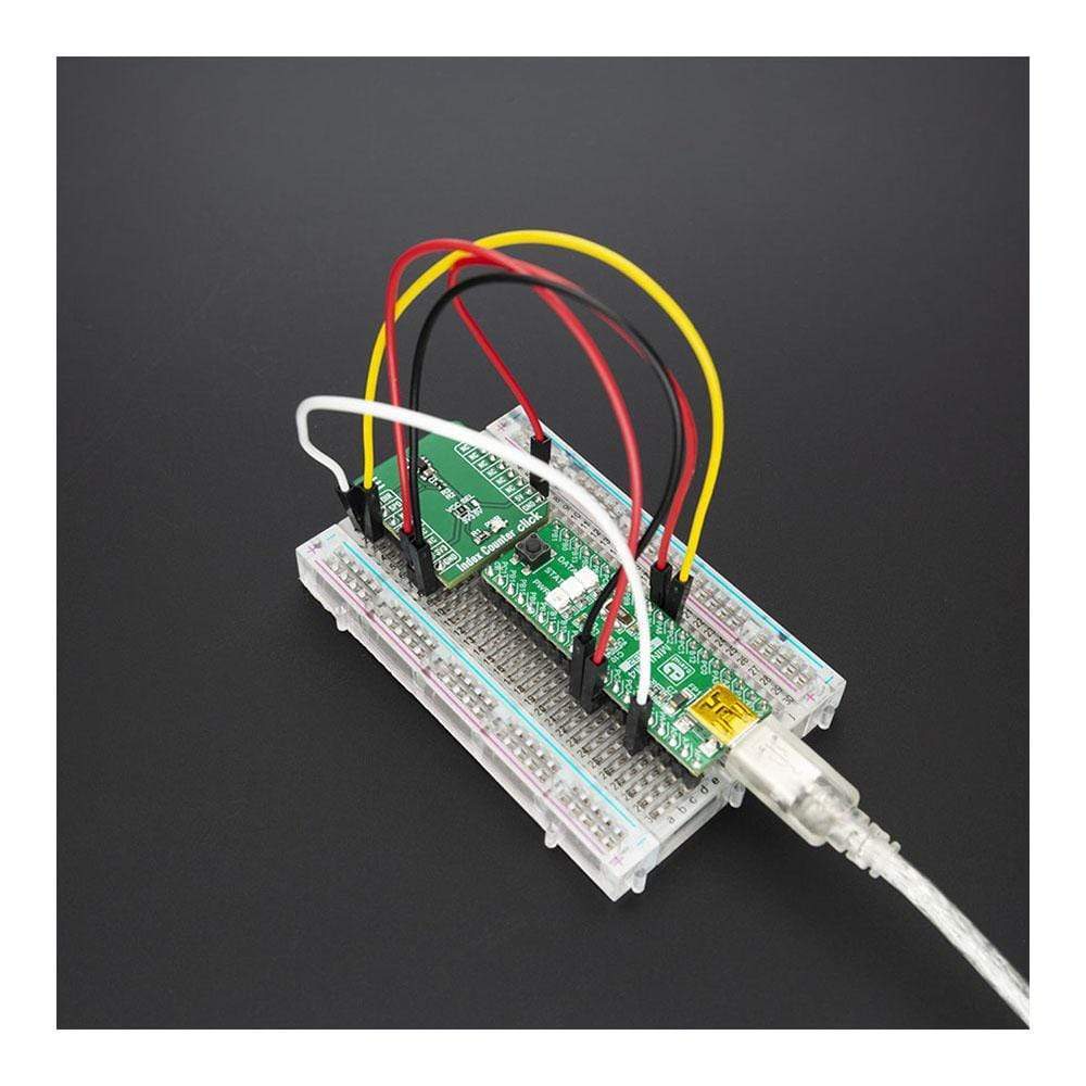
The Index Counter Click Board™ is supported by a mikroSDK compliant library, which includes functions that simplify software development. This Click Board™ comes as a fully tested product, ready to be used on a system equipped with the mikroBUS™ socket.
Downloads
How Does The Index Counter Click Board™ Work?
The Index Counter Click Board™ is based around the TLE4966K, which is a high sensitivity and high stability of the magnetic switching points sensor with reverse battery protection (-18 V). This sensor has many features that make it a perfect solution for small designs such as the Index Counter Click Board™. One of these features is certainly its high level of integration that allows a minimal number of external components.
.jpg)
The TLE4966K provides excellent temperature compensation capability for keeping the output stable under changing temperature. It is designed specifically for highly accurate applications with a speed signal for every magnetic pole pair, as well as direction information. The TLE4966 Hall Sensors feature two integrated and calibrated sensor elements for detecting direction and counting indexes. This feature eliminates the need for a second sensor and cuts engineering and production costs. Using just one sensor also raises system quality and reliability.
The chopped Double Hall Switch comprises two Hall probes, bias generator, compensation circuits, oscillator, and output transistors.
The bias generator provides currents for the Hall probes and the active circuits. Compensation circuits stabilize the temperature behavior and reduce technology variations.
The Active Error Compensation rejects offsets in signal stages and the influence of mechanical stress to the Hall probes caused by molding and soldering processes and other thermal stresses in the package. This chopper technique together with the threshold generator and the comparator ensures high accurate magnetic switching points.
SPECIFICATIONS
| Type | Magnetic,Optical |
| Applications | The Index Counter Click Board™ is excellent choice for applications such as index counting, rotational speed and direction applications, motor driven position systems. |
| On-board modules | TLE4966K, an integrated circuit double Hall-effect sensor |
| Key Features | High sensitivity and high stability of the magnetic switching points, reverse battery protection (-18 V), superior temperature stability |
| Interface | GPIO |
| Compatibility | mikroBUS |
| Click board size | S (28.6 x 25.4 mm) |
| Input Voltage | 3.3V or 5V |
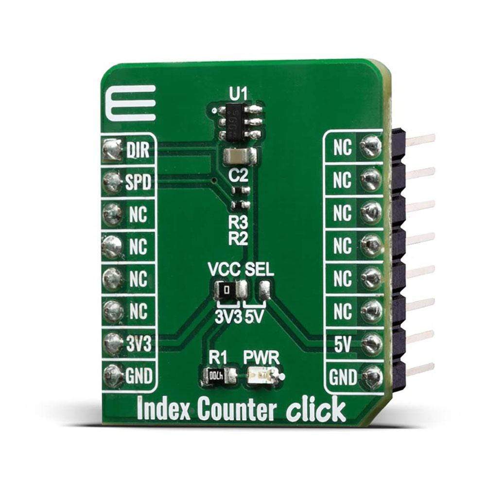
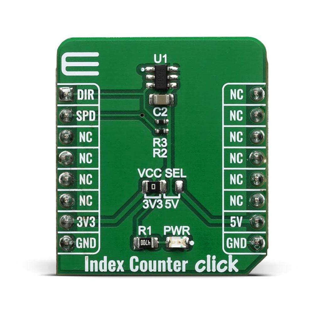
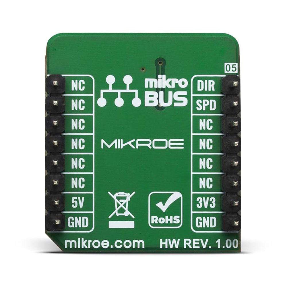
PINOUT DIAGRAM
This table shows how the pinout of the Index Counter Click Board™ corresponds to the pinout on the mikroBUS™ socket (the latter shown in the two middle columns).
| Notes | Pin | Pin | Notes | ||||
|---|---|---|---|---|---|---|---|
| Direction | DIR | 1 | AN | PWM | 16 | NC | |
| Speed | SPD | 2 | RST | INT | 15 | NC | |
| NC | 3 | CS | RX | 14 | NC | ||
| NC | 4 | SCK | TX | 13 | NC | ||
| NC | 5 | MISO | SCL | 12 | NC | ||
| NC | 6 | MOSI | SDA | 11 | NC | ||
| Power Supply | 3.3V | 7 | 3.3V | 5V | 10 | 5V | Power Supply |
| Ground | GND | 8 | GND | GND | 9 | GND | Ground |
ONBOARD SETTINGS AND INDICATORS
| Label | Name | Default | Description |
|---|---|---|---|
| LD1 | PWR | - | Power LED Indicator |
| JP1 | VCC SEL | Left | Power supply voltage selection: left position 3V3, right position 5V |
| General Information | |
|---|---|
Part Number (SKU) |
MIKROE-4005
|
Manufacturer |
|
| Physical and Mechanical | |
Weight |
0.016 kg
|
| Other | |
EAN |
8606018718320
|
Frequently Asked Questions
Have a Question?
Be the first to ask a question about this.