


Mikroelektronika d.o.o.
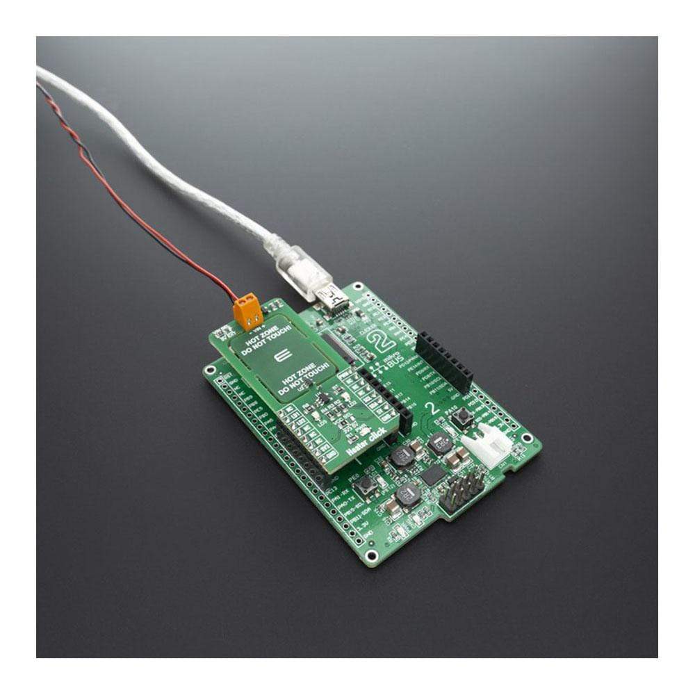
Heater Click Board™
Heater Click Board™
SKU: MIKROE-3996
Couldn't load pickup availability


Overview
The Heater Click Board™ is designed with intention of PCB heater concept testing and a useful tool for heating complete casing where staying in a specified temperature range is crucial. The exact PCB temperature can be set and controlled using a TMP235 onboard temperature sensor from Texas Instruments. Heater Click is a useful tool for some projects and products that require some kind of heating, whether to prevent electronics from becoming too cold, to help control humidity, to heat up a substance, or even to prevent one material from sticking to another.
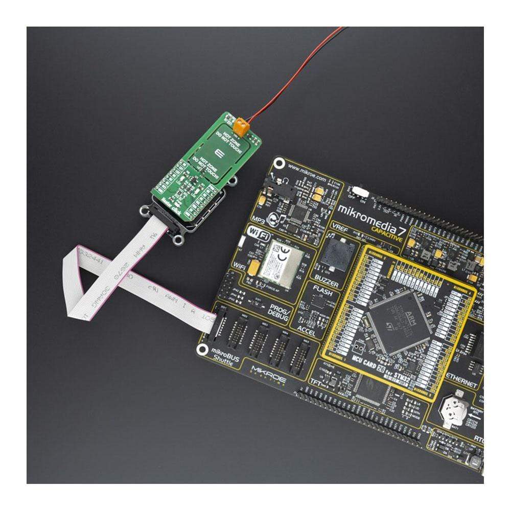
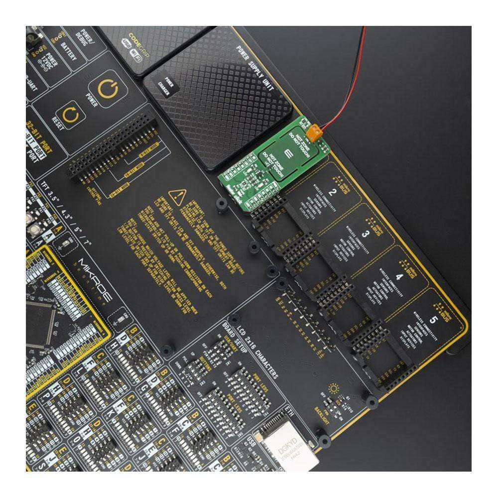
The Heater Click Board™ is supported by a mikroSDK compliant library, which includes functions that simplify software development. This Click Board™ comes as a fully tested product, ready to be used on a system equipped with the mikroBUS™ socket.
Downloads
How Does The Heater Click Board™ Work?
The Heater Click Board™ works on a principle of Joule heating, also known as resistance heating (resistive heating), a process by which the passage of an electric current through a conductor produces heat. Energy dissipated per unit time is equal to current passing through resistor times electric potential difference.
.jpg)
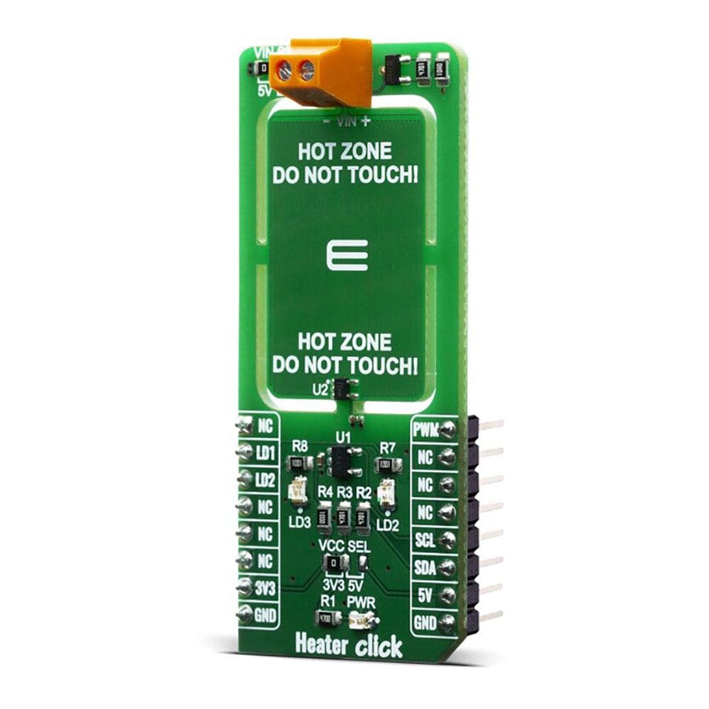
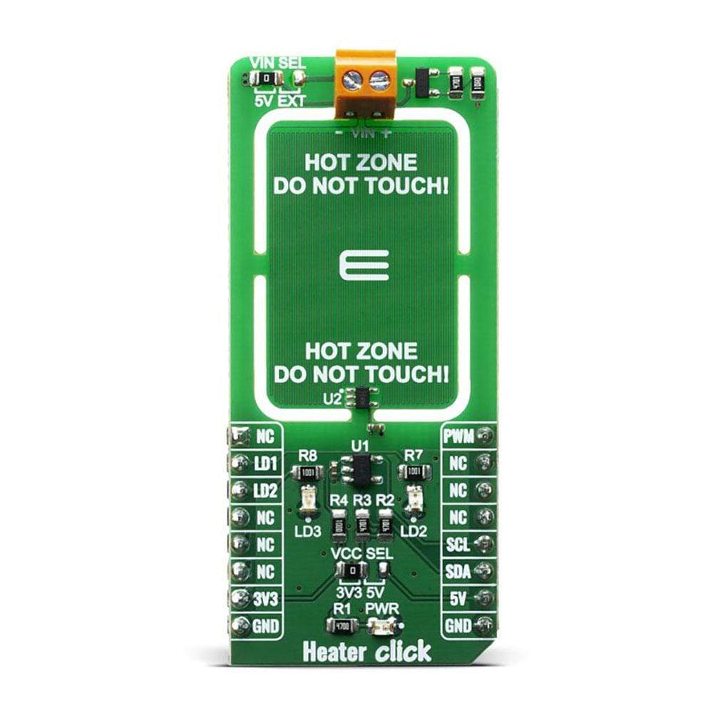
The Heater Click Board™ allows PCB temperature adjusting and monitoring as it have embedded trace resistor on top layer of PCB. Resistor is made from copper 1oz thick and a pattern of 0.1mm wide track 1950mm long, this give us about 10 ohm resistance at 25 degrees Celsius.
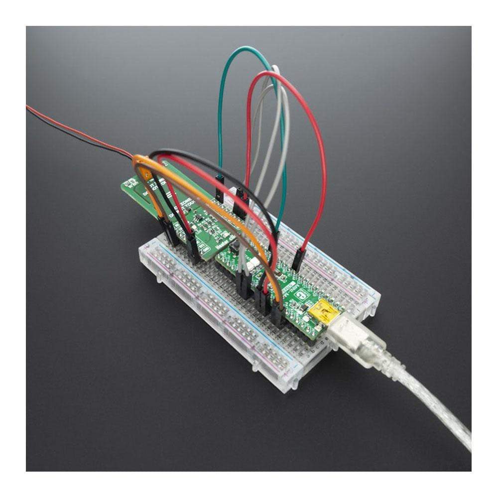
With on board VIN SEL jumper power supply can be selected as 5V from mikroBUS or any other voltage from external power supply at terminal block VIN. Using mikroBUS PWM pin power dissipation can be adjusted and therfore temperature controlled.
Heater Click minimize temperature spread from embedded resistor by having PCB gaps between it and rest of the click bord and components, by doing so hot zone is easier to warm up and keeping it at exact temperature without affecting rest of the commponents. LEDs are connected to LD1 and LD2 GPIO pins and can be used for example to signal user if temperature is ramping up or achieved, or any other user defined signaling.
Since the temperature rise in a heater is a function of its resistance and voltage, you don't always need to design a heater from scratch. So long as you can apply a specific voltage, you should be able to achieve your desired temperature and monitoring it through I2C.
Temperature is monitored with TMP235 precision CMOS integrated-circuit linear analog temperature sensor with an output voltage proportional to temperature, The TMP235 device provides a positive slope output of 10 mV/°C over the full –40°C to +150°C temperature range. Using MCP3221 a 12-bit ADC, output voltage from temperature sensor can be red through I2C. Communication to the MCP3221 is performed using a 2-wire, I2C compatible interface. Standard (100 kHz) and Fast (400 kHz) I2C modes are available with the device.
SPECIFICATIONS
| Type | Temperature |
| Applications | Seed germination, 3D printer heated beds, humidity control, loads, heater reference |
| On-board modules | MCP3221, TMP235 |
| Key Features | Stable temperature adjusting and monitoring |
| Interface | I2C,PWM |
| Compatibility | mikroBUS |
| Click board size | L (57.15 x 25.4 mm) |
| Input Voltage | 3.3V or 5V |
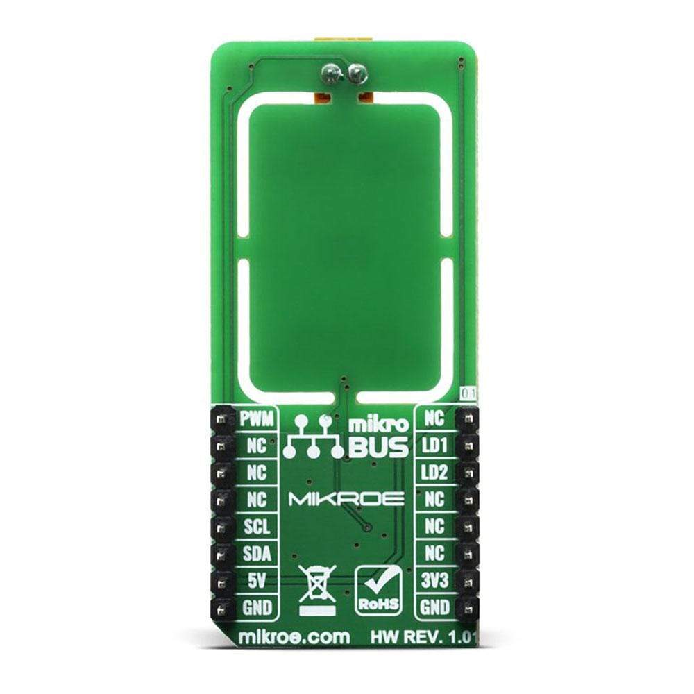
PINOUT DIAGRAM
This table shows how the pinout of the Heater Click Board™ corresponds to the pinout on the mikroBUS™ socket (the latter shown in the two middle columns).
| Notes | Pin | Pin | Notes | ||||
|---|---|---|---|---|---|---|---|
| NC | 1 | AN | PWM | 16 | PWM | Pulse width modulation | |
| Red Led | LD1 | 2 | RST | INT | 15 | NC | |
| Blue Led | LD2 | 3 | CS | RX | 14 | NC | |
| NC | 4 | SCK | TX | 13 | NC | ||
| NC | 5 | MISO | SCL | 12 | SCL | I2C Clock | |
| NC | 6 | MOSI | SDA | 11 | SDA | I2C Data | |
| Power Supply | 3.3V | 7 | 3.3V | 5V | 10 | 5V | Power supply |
| Ground | GND | 8 | GND | GND | 9 | GND | Ground |
ONBOARD SETTINGS AND INDICATORS
| Label | Name | Default | Description |
|---|---|---|---|
| PWR | Green Led | - | Power LED Indicator |
| LD2 | Red Led | - | Red LED Indicator |
| LD3 | Blue Led | - | Blue LED Indicator |
| General Information | |
|---|---|
Part Number (SKU) |
MIKROE-3996
|
Manufacturer |
|
| Physical and Mechanical | |
Weight |
0.019 kg
|
| Other | |
EAN |
8606018718399
|
Frequently Asked Questions
Have a Question?
Be the first to ask a question about this.