


Mikroelektronika d.o.o.
Step Down 2 Click Board™
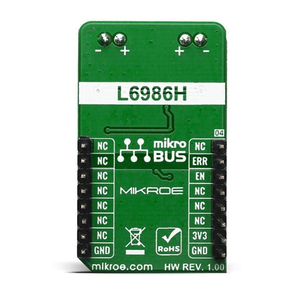
Step Down 2 Click Board™
SKU: MIKROE-3895
Couldn't load pickup availability


Overview
The Step Down 2 Click Board™ is fitted with the L6986HTR, a synchronous step-down switching regulator with operating input voltages from 4V to 38V and output voltage adjustability ranges from 0.85 V to VIN. Because of its features' main possibilities, the Step Down 2 Click Board™is ideally used for programmable logic controllers (PLCs), decentralized intelligent nodes, sensors, and low noise applications (LNM).
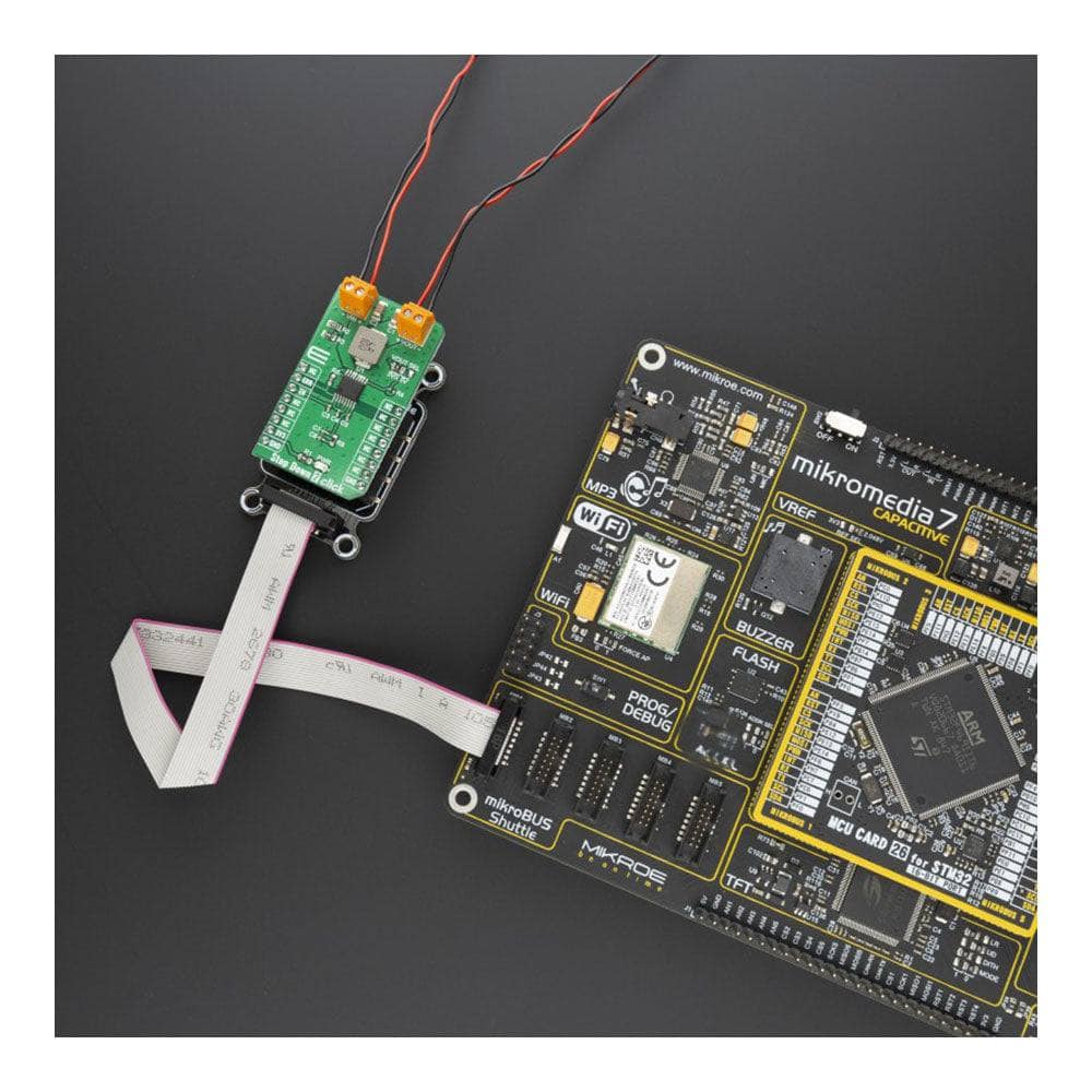
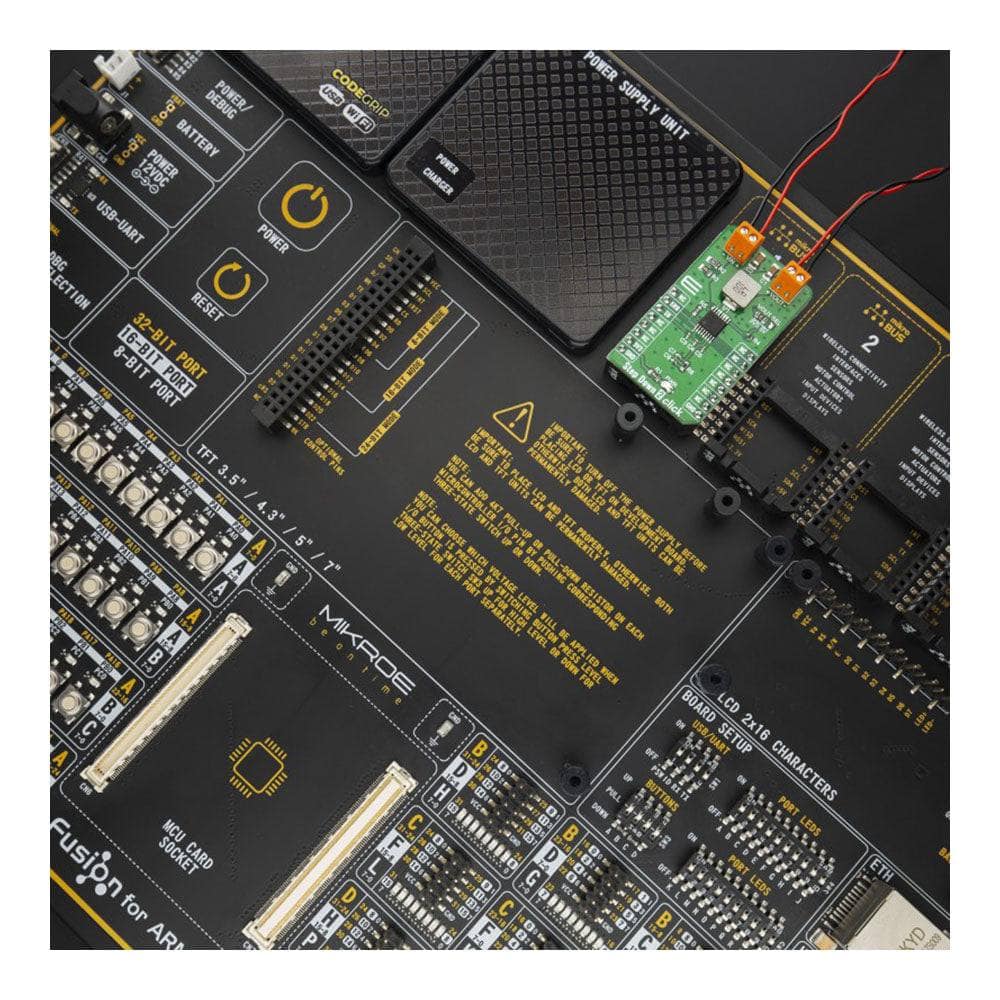
The Step Down 2 Click Board™ is supported by a mikroSDK compliant library, which includes functions that simplify software development. This Click Board™ comes as a fully tested product, ready to be used on a system equipped with the mikroBUS™ socket.
Downloads
How Does The Step Down 2 Click Board™ Work?
The L6986HTR is a step-down monolithic switching regulator able to deliver up to 2 A DC from STMicroelectronics. The output voltage adjustability ranges from 0.85 V to VIN. The "low consumption mode" (LCM) is designed for applications active during idle mode, so it maximizes the efficiency at light-load with controlled output voltage ripple. The "low noise mode" (LNM) makes the switching frequency constant and minimizes the output voltage ripple overload current range, meeting the low noise application specifications.
The output voltage supervisor manages the reset phase for any digital load (µC, FPGA). The RST open collector output can also implement output voltage sequencing during the power-up phase. The synchronous rectification, designed for high efficiency at medium - heavy load, and the high switching frequency capability make the size of the application compact. Pulse by pulse current sensing on both power elements implements an effective constant current protection.
The L6986H device is based on a "peak current mode", constant frequency control. Consequently, the intersection between the error amplifier output and the sensed inductor current generates the PWM control signal to drive the power switch. The device features LNM (low noise mode) which implements a forced PWM operation over the different loading conditions. The LNM features a constant switching frequency to minimize the noise in the final application and a constant voltage ripple at fixed VIN. The regulator in steady loading conditions never skips pulses and it operates in continuous conduction mode (CCM) over the different loading conditions, thus making this operation mode ideal for noise-sensitive applications.
The overvoltage protection monitors the VOUT pin and enables the low-side MOSFET to discharge the output capacitor if the output voltage is 20% over the nominal value. This is a second level protection and should never be triggered in normal operating conditions if the system is appropriately dimensioned. In other words, the selection of the external power components and the dynamic performance determined by the compensation network should guarantee an output voltage regulation within the overvoltage threshold even during the worst case scenario in term of load transitions. The protection is reliable and can operate even during normal load transitions for a system whose dynamic performance is not in line with the load dynamic request. As a consequence, the output voltage regulation would be affected.
Because of its features' main possibilities, the Step Down 2 Click Board™ is ideally used for programmable logic controllers (PLCs), decentralized intelligent nodes, sensors, and low noise applications (LNM).
SPECIFICATIONS
| Type | Buck |
| Applications | Programmable logic controllers (PLCs), decentralized intelligent nodes, sensors, and low noise applications (LNM) |
| On-board modules | L6986HTR, a synchronous step-down switching regulator from STMicroelectronics |
| Key Features | Low consumption mode, Overvoltage protection, Embedded output voltage supervisor |
| Interface | GPIO |
| Compatibility | mikroBUS |
| Click board size | M (42.9 x 25.4 mm) |
| Input Voltage | 3.3V |
PINOUT DIAGRAM
This table shows how the pinout of the Step Down 2 Click Board™ corresponds to the pinout on the mikroBUS™ socket (the latter shown in the two middle columns).
| Notes | Pin | Pin | Notes | ||||
|---|---|---|---|---|---|---|---|
| NC | 1 | AN | PWM | 16 | NC | ||
| Error | ERR | 2 | RST | INT | 15 | NC | |
| Enable | EN | 3 | CS | RX | 14 | NC | |
| NC | 4 | SCK | TX | 13 | NC | ||
| NC | 5 | MISO | SCL | 12 | NC | ||
| NC | 6 | MOSI | SDA | 11 | NC | ||
| Power Supply | 3.3V | 7 | 3.3V | 5V | 10 | NC | |
| Ground | GND | 8 | GND | GND | 9 | GND | Ground |
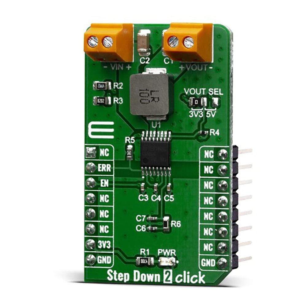
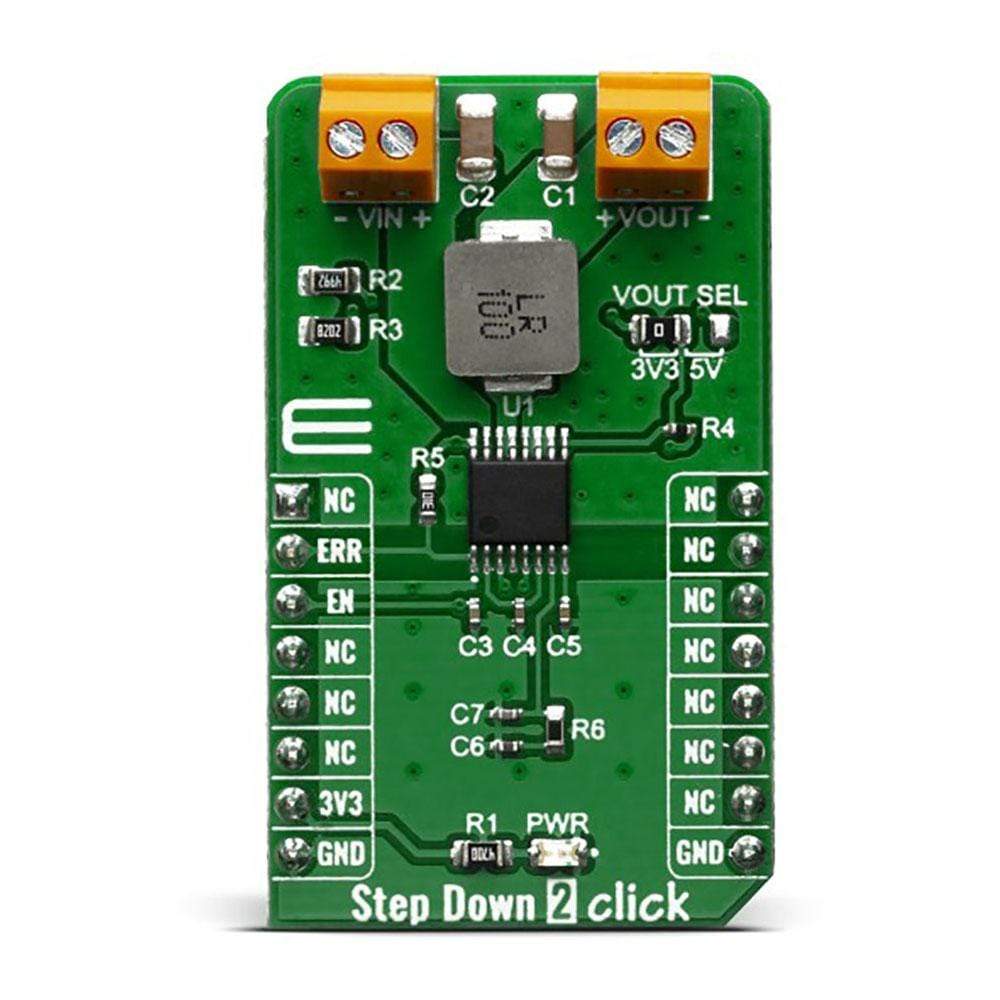
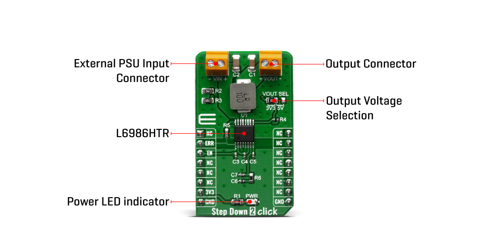
ONBOARD SETTINGS AND INDICATORS
| Label | Name | Default | Description |
|---|---|---|---|
| LD1 | PWR | - | Power LED Indicator |
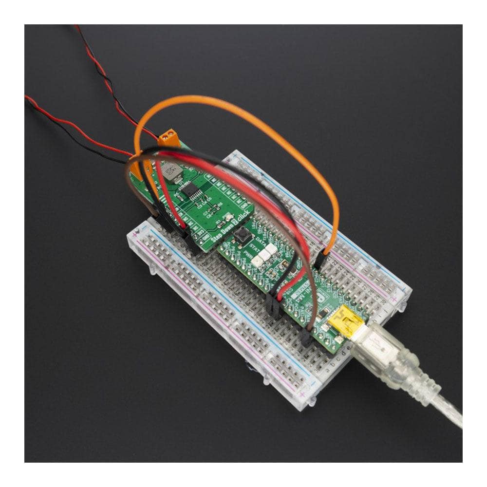
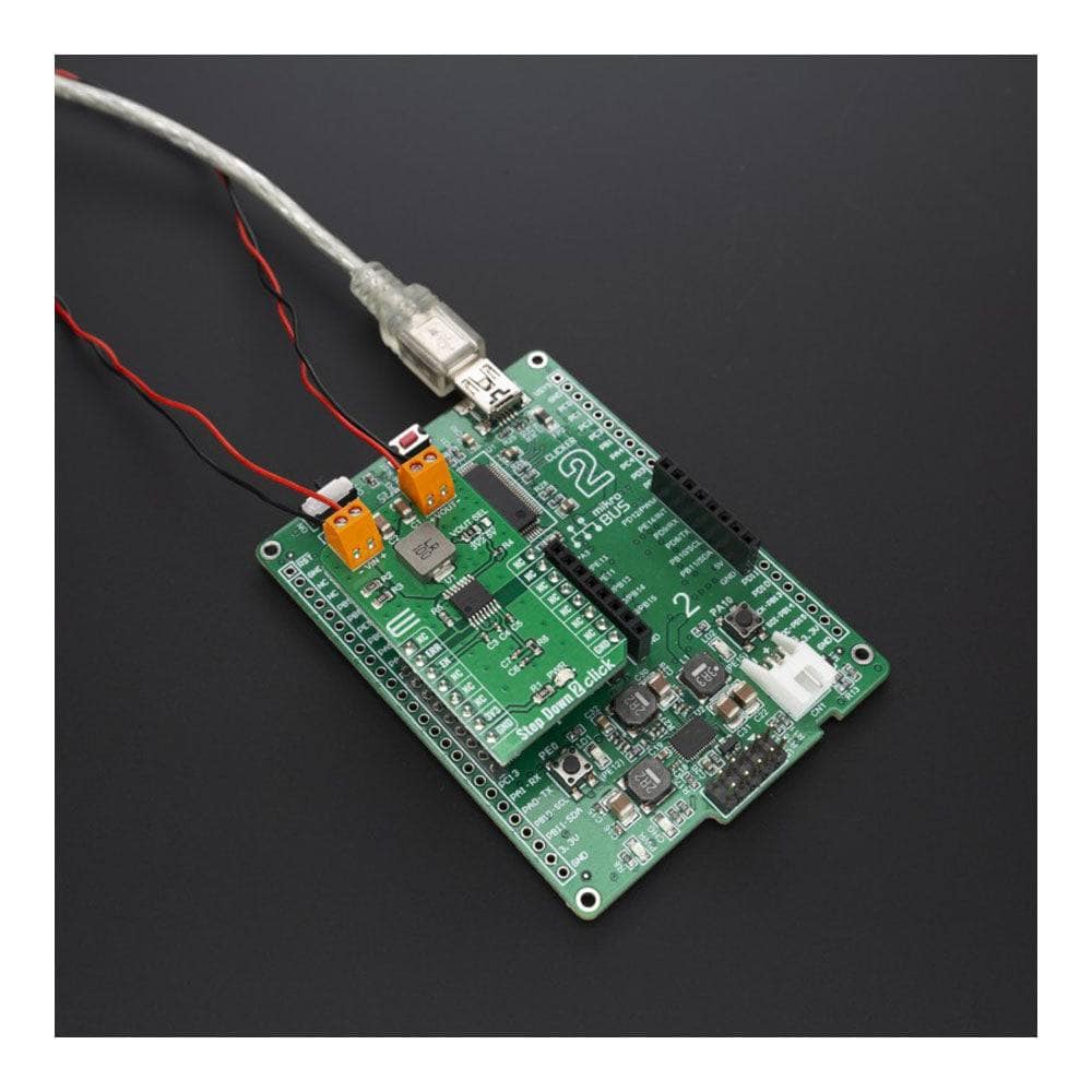
| TB1 | VIN | - | Input terminal for connecting the external power source |
| TB2 | VOUT | - | Output terminal for connecting the load |
| JP1 | VOUT SEL | Left | Output voltage selection: Left position 3.3V, right position 5V |
STEP DOWN 2 CLICK ELECTRICAL SPECIFICATIONS
| Description | Min | Typ | Max | Unit |
|---|---|---|---|---|
| Input voltage | 4 | - | 38 | V |
| Output voltage | 0.85 | - | VIN | V |
| Output current | -30 | - | 2 | A |
| General Information | |
|---|---|
Part Number (SKU) |
MIKROE-3895
|
Manufacturer |
|
| Physical and Mechanical | |
Weight |
0.019 kg
|
| Other | |
EAN |
8606018719211
|
Frequently Asked Questions
Have a Question?
Be the first to ask a question about this.