


Mikroelektronika d.o.o.
DAC 7 Click Board™
DAC 7 Click Board™
SKU: MIKROE-3886
Couldn't load pickup availability
Overview
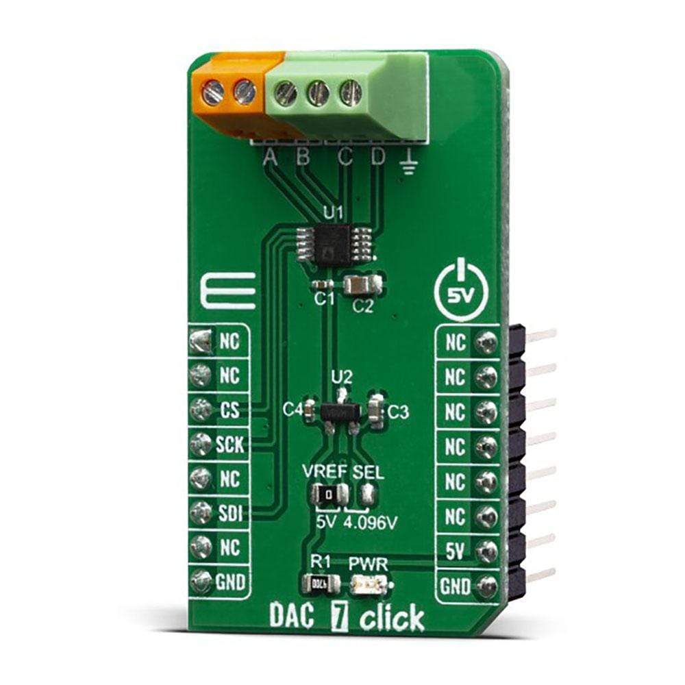
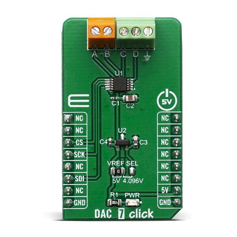
The DAC 7 Click Board™ carries the AD5624R, a low-power four-channel, 12-bit buffered Digital-to-Analog Converter. AD5624R converts the digital value to the corresponding voltage level using an external voltage reference. This will help you convert digital information from the mainboard to four analogue outputs on the DAC 7 Click Board™. For that purpose, DAC 7 Click Board™ uses MCP1541, which is a low-dropout precision voltage reference with a 4.096V output voltage.
With all those possibilities on board, DAC 7 Click Board™ makes a perfect choice for an accurate and simple generation of analogue signals for various purposes, such as programmable Power Supplies, Laser Drivers, Projectors, IP Network cameras, autofocus digital still camera lens, and more
Downloads
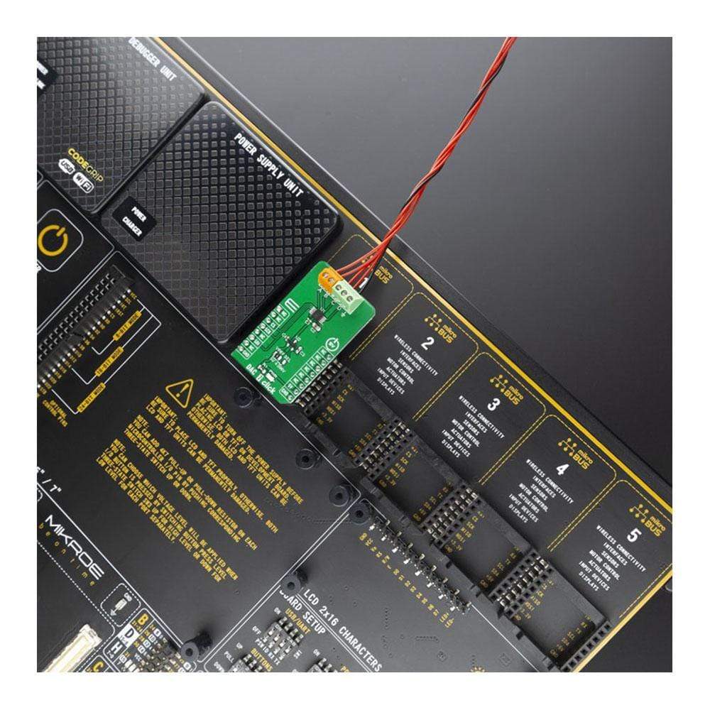
How Does The DAC 7 Click Board™ Work?
The DAC 7 Click Board™ is an advanced 12-bit, four-channel digital to analogue converter (DAC). This device communicates with the main MCU through the is compatible with standard SPI, QSPI™, MICROWIRE™, and DSP interface standards. Also, there is a selectable voltage reference as well with onboard jumpers which makes this click more open for specific projects.
The main active component on the DAC 7 Click Board™ is the AD5624R from Analog Devices. This is a low power, four-channel, 12-bit voltage output Digital-To-Analog Converter (DAC). It is specified monotonic by design across a wide power supply range from 2.7 V to 5.5 V. Using an external reference, the AD5624R provides a full-scale output voltage in the range from 0V to Vref, while consuming 0.1 mA quiescent current per channel. The AD5624R also includes per channel, user-programmable, power down registers facilitate the DAC output buffers to start in a power down to 10K state and remain in this state until a power-up command is issued to these output buffers.
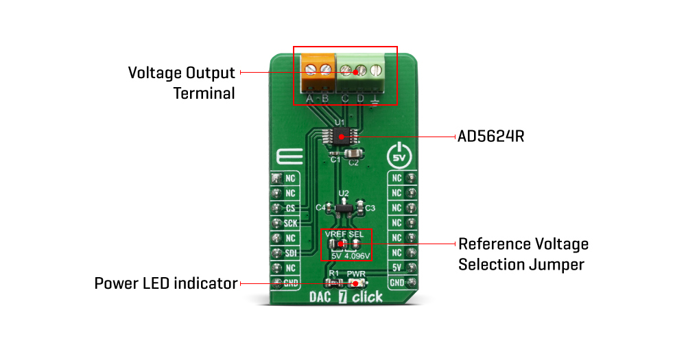
The DAC 7 Click Board™ has a high precision voltage reference included onboard. For that purpose, we have used 4.096V precision voltage reference MCP1541 from Microchip. This little SOT23 device is stable with capacitive loads. It has regulations for both sink and source and is very accurate. This gives DAC 7 click good flexibility for use in various applications.
Low quiescent current, wide power supply range, and per-channel power down option makes AD5624R ideal for low power, battery-operated system. The device communicates through the SPI interface. Besides the standard SPI, QSPI™, MICROWIRE™, and DSP interface standards are also supported. However, this click board™ is using standard SPI communication with the main MCU.
The reference voltage level can be selected via VREF SEL jumper, between 4.096V and 5V. This allows for both 4.096V and 5V Voltage outputs from DAC 7 click can be connected through a 9-terminal block where the first is common GND and the last eight are VOUTA to VOUTH.
The DAC 7 Click Board™ is designed to be operated only with a 5V logic level. A proper logic voltage level conversion should be performed before the Click board™ is used with MCUs with logic levels of 3.3V.
Specifications
| Type | DAC |
| Applications | Suitable for programmable power supplies, programable window comparator, VCOM biasing in display panel, laser driver in multifunction printers, autofocus digital still camera lens, ATM machines, currency counters, barcode readers, IP network cameras, projectors |
| On-board modules | AD5624R- a low power, four-channel, 12-bit voltage output Digital-To-Analog Converter (DAC) from Analog Devices; and MCP1541 - a 4.096V precision voltage reference IC, from Microchip. |
| Key Features | High precision voltage reference, low power consumption, high-speed SPI interface, 12bit resolution, reference voltage selection |
| Interface | SPI |
| Compatibility | mikroBUS |
| Click board size | M (42.9 x 25.4 mm) |
| Input Voltage | 5V |
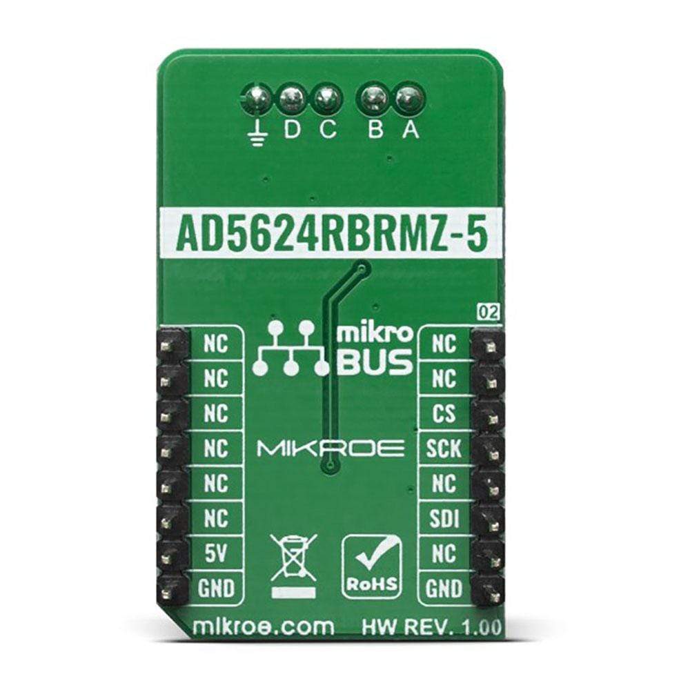
Pinout Diagram
This table shows how the pinout on the DAC 7 Click Board™ corresponds to the pinout on the mikroBUS™ socket (the latter shown in the two middle columns).
| Notes | Pin | Pin | Notes | ||||
|---|---|---|---|---|---|---|---|
| NC | 1 | AN | PWM | 16 | NC | ||
| NC | 2 | RST | INT | 15 | NC | ||
| SPI Chip Select | CS | 3 | CS | RX | 14 | NC | |
| SPI Clock | SCK | 4 | SCK | TX | 13 | NC | |
| NC | 5 | MISO | SCL | 12 | NC | ||
| SPI Data IN | SDI | 6 | MOSI | SDA | 11 | NC | |
| NC | 7 | 3.3V | 5V | 10 | 5V | Power Supply | |
| Ground | GND | 8 | GND | GND | 9 | GND | Ground |
Onboard settings and indicators
| Label | Name | Default | Description |
|---|---|---|---|
| JP1 | VREF SEL | Left | DAC Reference Voltage Selection 4.096/5V, left position 4.096, right position 5V |
| LD1 | PWR | - | Power LED indicator |
| General Information | |
|---|---|
Part Number (SKU) |
MIKROE-3886
|
Manufacturer |
|
| Physical and Mechanical | |
Weight |
0.019 kg
|
| Other | |
EAN |
8606018719273
|
Frequently Asked Questions
Have a Question?
Be the first to ask a question about this.