


Mikroelektronika d.o.o.
Step Up Click Board™
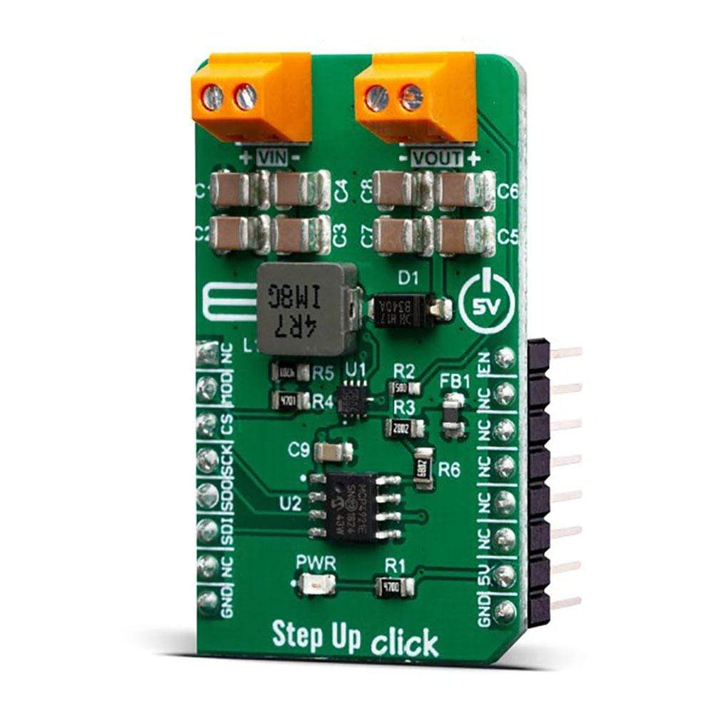
Step Up Click Board™
SKU: MIKROE-3709
Couldn't load pickup availability
Overview
The Step Up Click Board™ is a fixed frequency DC-DC step-up (boost) regulator, which can be obtained from any low voltage input - such as NiCd, NiMH or one cell Li-Po/Li-Ion batteries. This click features very high efficiency, low noise and anti-ringing voltage output and inrush current limiting with the internal soft-start, as well as true disconnect option for minimized power drain, when in shutdown mode. These features allow this device to be used as the power source for various battery-operated devices, such as microcontrollers, various portable embedded electronic devices, handheld instruments, GPS modules, or various battery-operated USB emergency backup chargers. Very good switching efficiency factor ensures prolonged battery life for any application this device is used in.
The Step Up Click Board™ is supported by a mikroSDK compliant library, which includes functions that simplify software development. This Click Board™ comes as a fully tested product, ready to be used on a system equipped with the mikroBUS™ socket.
Downloads
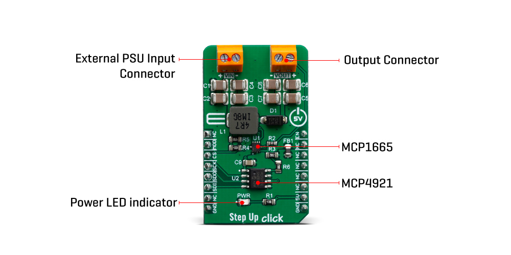
The Step Up Click Board™ carries the MCP1665, a high-voltage, 3.6A, integrated switch PFM/PWM boost regulator, available in a 2mm x 2mm VQFN® package, from Microchip. Boost click provides an adjustable output voltage through the onboard DAC that drives the FB pin of the MCP1665 to set desired output voltage. The input voltage can be in range from 2.9V to 5V V from an external DC source connected to VIN screw terminal. The output voltage can be set up to 32V.
How Does The Step Up Click Board™ Work?
The Step Up Click Board™ utilizes the MCP1665, a 500 kHz, compact, high-efficiency, fixed-frequency, nonsynchronous step-up DC-DC converter that integrates a 36V, 100 mΩ NMOS switch, from Microchip. This IC is targeted towards boosting the voltage from NiCd, NiMH, Li-Po/Li-Ion batteries and as such it has a great efficiency factor, that allows for prolonged battery life. The MCP1665 IC uses the fixed switching frequency of 500 kHz and has the overvoltage protection to ensure safe operation.
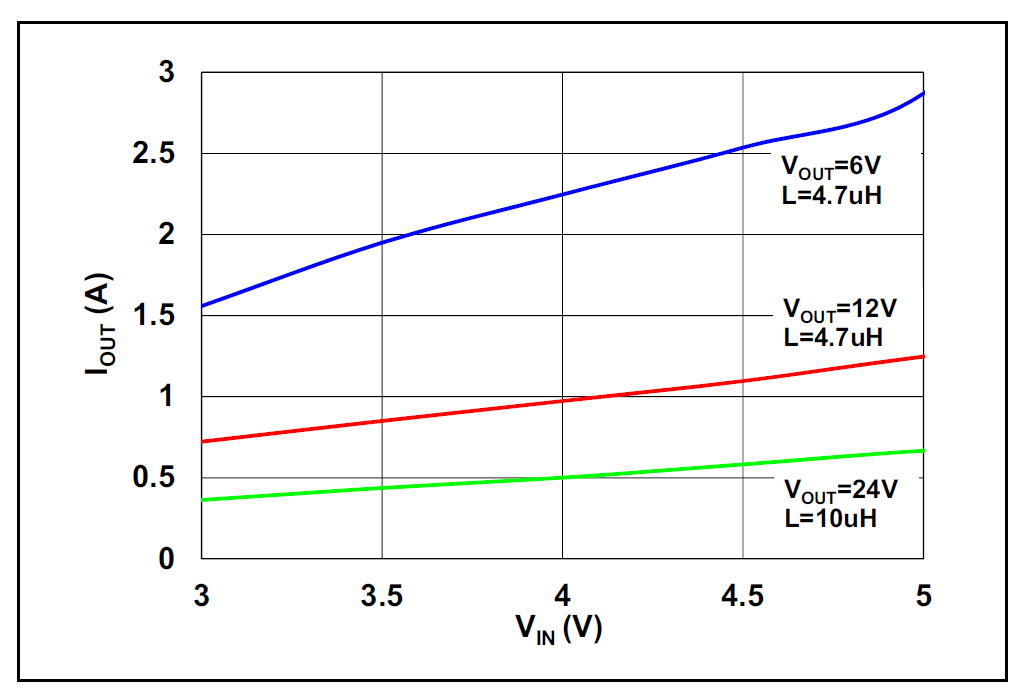
Thanks to the under-voltage lockout feature, the voltage step-up process starts with the input voltage as low as 2.7V. MCP1665 features an UVLO that prevents fault operation below 2.7V, which corresponds to the value of three discharged primary Ni-Cd cells. The device starts its normal operation at 2.85V (typical) input. For the optimal efficiency, the device should be powered with at least 2.85V at the input terminal. Output current depends on the input and desired output voltage. For example, when powered with 4V at the input, Step Up click will be able to deliver about 1A @ 12V to the connected load. As with the most step-up regulators, the input voltage should always be less than the voltage at the output to maintain the proper regulation. On the diagram below, the dependence of the maximum output current (Iout) on the input and typical output voltages is given.
The MCP1665 step-up regulator actively damps the oscillations typically found at the switch node of a boost converter. This removes the high-frequency radiated noise, ensuring low noise operation.
Besides the MCP1665, Step Up 2 click also contains the D/A converter (DAC) labelled as MCP4921, 12-Bit DACs with the SPI Interface by Microchip, which is used in feedback loop. The DACs is connected to the feedback loop of the boost converter and therefore, the DAC signal which commonly ranges from 0 to +VREF, influences the voltage on the feedback midpoint. That way, the output voltage can be set to a desired value, up to 30V. The mentioned DAC uses SPI communication so the SDI, SDO, SCK, and CS pin of the mikroBUS™ are used for communication with the main MCU.
The device also features the mode pin, labelled as MOD, which is constructed as the open-drain output, that is pulled HIGH by the onboard 10K resistor. This allows an easy interfacing with the MCU and a simple solution to have the control over the switching mode. When the MOD pin is set to logic high level, the device is switching in PFM for light load. The MOD pin is routed to the mikroBUS™ RST pin
Besides the mode pin, the EN pin used to enable the device is routed to the mikroBUS™ CS pin. When pulled LOW, this pin will engage the true disconnect of the output load option, resulting in very low quintessential currents, suitable for the battery-operated devices. This pin is also pulled HIGH by the onboard resistor.
SPECIFICATIONS
| Type | Boost |
| Applications | Power source for various battery-operated devices, such as microcontrollers, various portable embedded electronic devices, handheld instruments, GPS modules, or various battery-operated USB emergency backup chargers |
| On-board modules | MCP1665, a high-voltage, 3.6A, integrated switch PFM/PWM boost regulator |
| Key Features | Compact, high-efficiency, fixed-frequency, nonsynchronous step-up DC-DC converter that integrates a 36V, 100 mΩ NMOS switch |
| Interface | SPI |
| Compatibility | mikroBUS |
| Click board size | M (42.9 x 25.4 mm) |
| Input Voltage | 5V |
PINOUT DIAGRAM
This table shows how the pinout of the Step Up Click Board™ corresponds to the pinout on the mikroBUS™ socket (the latter shown in the two middle columns).
| Notes | Pin | Pin | Notes | ||||
|---|---|---|---|---|---|---|---|
| NC | 1 | AN | PWM | 16 | EN | Enable Input | |
| Mode input | MOD | 2 | RST | INT | 15 | NC | |
| SPI Chip Select | CS | 3 | CS | RX | 14 | NC | |
| SPI Clock | SCK | 4 | SCK | TX | 13 | NC | |
| SPI Data Out | SDO | 5 | MISO | SCL | 12 | NC | |
| SPI Data In | SDI | 6 | MOSI | SDA | 11 | NC | |
| NC | 7 | 3.3V | 5V | 10 | 5V | Power Supply | |
| Ground | GND | 8 | GND | GND | 9 | GND | Ground |
ONBOARD SETTINGS AND INDICATORS
| Label | Name | Default | Description |
|---|---|---|---|
| LD1 | PWR | - | Power LED Indicator |
| TB1 | VIN | - | Input voltage terminal |
| TB2 | VOUT | - | Output voltage terminal |
| General Information | |
|---|---|
Part Number (SKU) |
MIKROE-3709
|
Manufacturer |
|
| Physical and Mechanical | |
Weight |
0.021 kg
|
| Other | |
EAN |
8606018716678
|
Frequently Asked Questions
Have a Question?
Be the first to ask a question about this.