

Mikroelektronika d.o.o.
Gyro 5 Click Board™
Gyro 5 Click Board™
SKU: MIKROE-3669
Couldn't load pickup availability


Overview
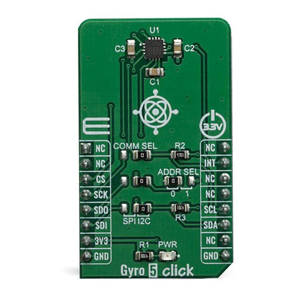
The Gyro 5 Click Board™ is a three-axis gyroscope Click Board™ that can sense motion over three perpendicular axes. It is equipped with the ITG-3701, a three-axis digital gyroscope. This IC incorporates microelectromechanical sensing elements (MEMS), produced using a proprietary CMOS micromachining technology. This technology allows for excellent stability and linearity over temperature. The angular data is available in a 16-bit format, along with the device’s die temperature data. Gyro 5 Click can be used for angular speed up to 4000 degrees per second (DPS), it features a FIFO buffer, two dedicated interrupt lines, and on-chip data processing for optimized firmware development.
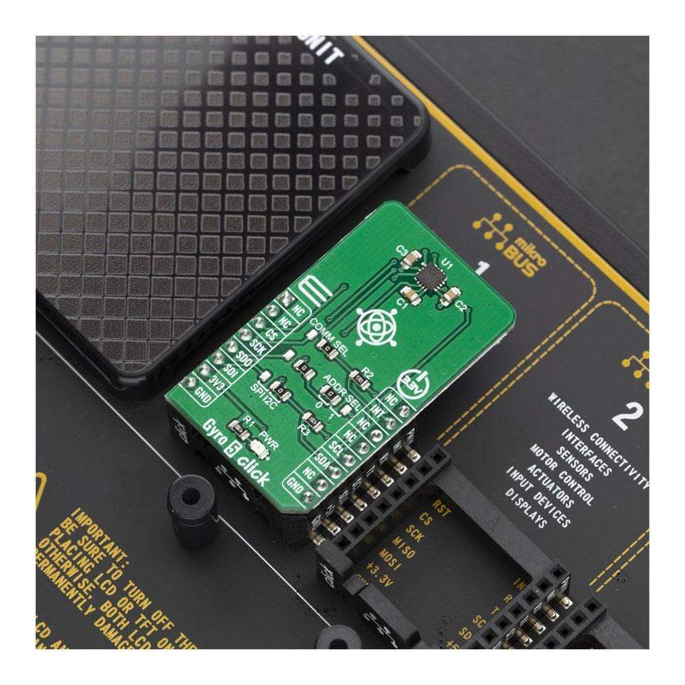
The Gyro 5 Click Board™ is supported by a mikroSDK compliant library, which includes functions that simplify software development. This Click Board™ comes as a fully tested product, ready to be used on a system equipped with the mikroBUS™ socket.
Downloads
The Gyro 5 Click Board™ is based on the ITG-3701 IC which supports both I2C and SPI interfaces, which allows Click Board™ to be interfaced with a wide range of different MCUs. Although it is very sensitive (down to 65.5 LSB/dps) it is very resistant to shock and has a non-linearity of only 0.3% of the full-scale value (FS). These features make the Gyro 5 Click Board™ a perfect solution for the development and testing of a wide range of applications which rely on an accurate angular rate sensing. This includes gyro-stabilization for various types of robots, drones, UAVs and RC vehicles, game controllers, orientation sensing, gesture-based HMI applications, VR glasses, and similar types of applications.
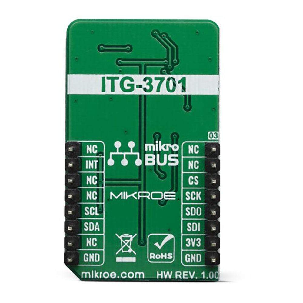
How Does The Gyro 5 Click Board™Work?
The Gyro 5 Click Board™ is based on the ITG-3701, a three-axis digital gyroscope sensor IC, by InvenSense Inc TDK Group Company. This device features factory calibrated scale factor, High cross-axis isolation via proprietary MEMS design and a precision clock with 1% drift from -40°C to 85°C, which results in a high level of integration, allowing very good linearity over temperature, and increased output stability when no motion. It also makes it resistant to shocks up to 10,000g, allowing it to be used for speeds up to 4000 dps. It supports signal conditioning including low-pass filtering, as well as the programmable interrupt.
Typically, higher dps range results in lower sensitivity. Therefore, the ITG-3701 allows to dynamically select the full-scale range (FSR) value in several discrete steps: ±500, ±1000, ±2000 and ±2000 dps. This allows optimized performance for a given usage scenario. For example, if used in applications with faster angle rates such as sports equipment monitoring (golf club or tennis racket), a higher FSR might be required, at a cost of lower sensitivity.
The MEMS output voltage is sampled by a high-accuracy 16-bit A/D converter, allowing the output in 2's complement format. As mentioned above, different FS ranges have different sensitivity per LSB. Therefore, raw output values of the sensor will have to be multiplied with the sensitivity to obtain the values in degrees per second (dps). These values can be obtained from the ITG-3701 datasheet, for every FS range, respectively.
The ITG-3701 sensor feature an internal programmable low-pass filter, with user-selectable cutoff frequency. The output signal can be digitally selected and applied to an angular speed measurement, allowing the developer to reduce the noise or fine-tune the sensitivity within a desired bandwidth.
The ITG-3701 device features a FIFO buffer, which in combination with a dedicated interrupt line, allows firmware optimizations while reducing the power consumption of the application as a result. The FIFO buffer has 32 slots, each 16-bit wide, used to store output values. The FIFO can lower the traffic on the serial bus interface, and reduce power consumption by allowing the system processor to burst read sensor data and then go into a low-power mode. A FIFO counter keeps track of how many bytes of valid data are contained in the FIFO. The FIFO register supports burst reads, while the interrupt function may be used to determine when new data is available.
The interrupt pin is routed to the mikroBUS™ INT pin (labelled as INT). This line is used to report one of the programmable FIFO events: watermark level is reached, FIFO buffer is empty, and there is an overrun event on the FIFO buffer (FIFO is full). The pin can also be used to report when there is a new data available at the output after the conversion period (data ready). To find out which event exactly has occurred, the host MCU should read the status of the respective flag bits from the INT_STATUS register.
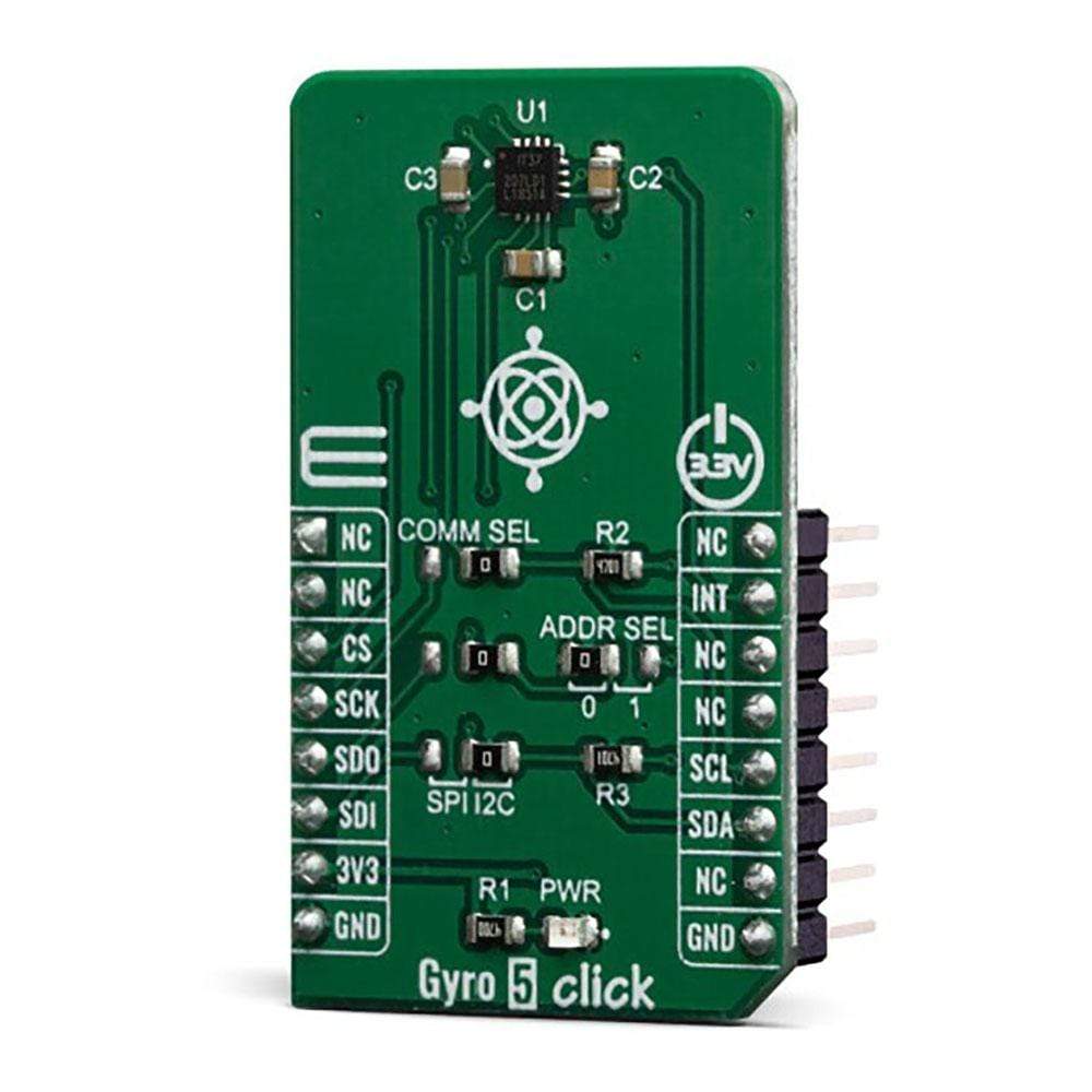
The Gyro 5 Click Board™ offers two communication interfaces. It can be used with either I2C or SPI. The onboard SMD jumpers labelled as COMM SEL allow switching between the two interfaces. Note that all the jumpers have to be positioned either I2C or to SPI position. When I2C interface is selected, an additional SMD jumper labelled as ADDR SEL becomes available, determining the least significant bit of the ITG-3701 slave I2C address.
The Gyro 5 Click Board™ can operate with 3.3V MCUs only, it is set to work over the I2C by default, and it is already equipped with the pull-up resistors. It is ready to be used as soon as it is inserted into a mikroBUS™ socket of the development system.
SPECIFICATIONS
| Type | Gyroscope,Motion |
| Applications | The Gyro 5 Click Board™ can be used to develop applications for gyro-stabilization of different types of robots, drones, UAVs and RC vehicles, game controllers, orientation sensing, gesture-based HMI applications, VR glasses, and similar types of applications. |
| On-board modules | ITG-3701, a three-axis digital gyroscope sensor IC, by InvenSense Inc. |
| Key Features | Advanced interrupt engine allows simplified firmware development and better system-wide power consumption, very good reliability, precision, and zero-level stability, signal conditioning in a form of low and high-pass filtering, both SPI and I2C interface… |
| Interface | I2C,SPI |
| Compatibility | mikroBUS |
| Click board size | M (42.9 x 25.4 mm) |
| Input Voltage | 3.3V |
PINOUT DIAGRAM
This table shows how the pinout of the Gyro 5 Click Board™ corresponds to the pinout on the mikroBUS™ socket (the latter shown in the two middle columns).
| Notes | Pin | Pin | Notes | ||||
|---|---|---|---|---|---|---|---|
| NC | 1 | AN | PWM | 16 | NC | ||
| NC | 2 | RST | INT | 15 | INT | Interrupt | |
| SPI Chip Select | CS | 3 | CS | RX | 14 | NC | |
| SPI Clock | SCK | 4 | SCK | TX | 13 | NC | |
| SPI Data OUT | SDO | 5 | MISO | SCL | 12 | SCL | I2C Clock |
| SPI Data IN | SDI | 6 | MOSI | SDA | 11 | SDA | I2C Data |
| Power Supply | 3.3V | 7 | 3.3V | 5V | 10 | NC | |
| Ground | GND | 8 | GND | GND | 9 | GND | Ground |
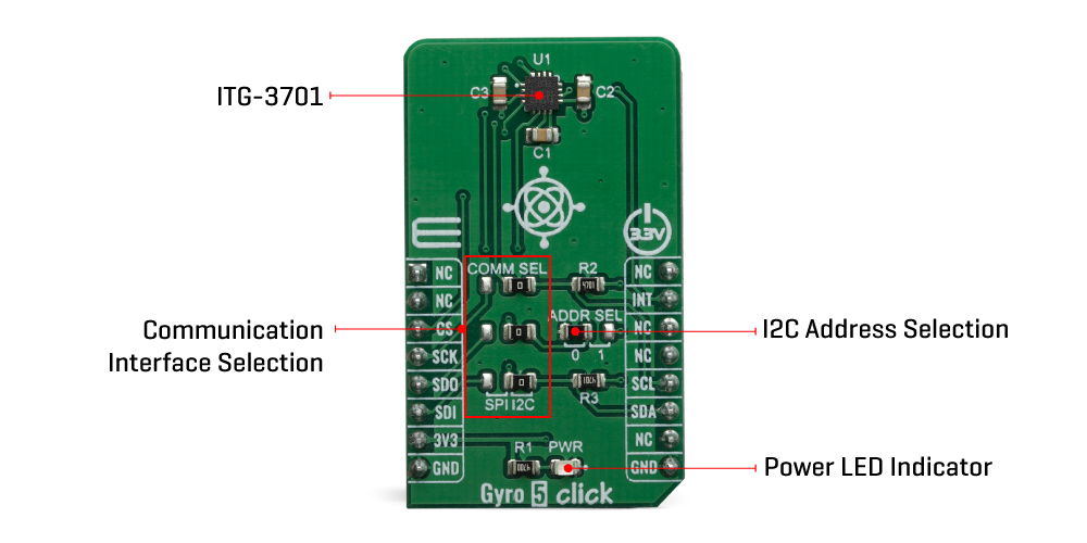
ONBOARD SETTINGS AND INDICATORS
| Label | Name | Default | Description |
|---|---|---|---|
| PWR | PWR | - | Power LED Indicator |
| JP1-JP3 | SEL COMM | Right | Communication interface selection: left position SPI, right position I2C |
| JP4 | I2C ADD | Left | I2C address LSB selection: left position 0, right position 1 |
| General Information | |
|---|---|
Part Number (SKU) |
MIKROE-3669
|
Manufacturer |
|
| Physical and Mechanical | |
Weight |
0.018 kg
|
| Other | |
EAN |
8606018716494
|
Frequently Asked Questions
Have a Question?
Be the first to ask a question about this.