


Mikroelektronika d.o.o.
AudioAMP 5 Click Board™
AudioAMP 5 Click Board™
SKU: MIKROE-3401
Couldn't load pickup availability


Key Features
Overview
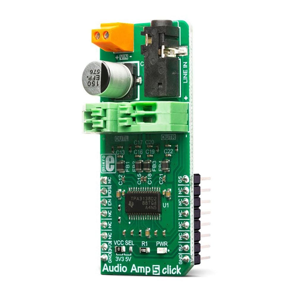
The AudioAmp 5 Click Board™ is a stereo audio amplifier, capable of delivering up to 10W per channel with an 8Ω load. It is based on the TPA3138D2, a class-D integrated amplifier, which utilises a highly efficient switching scheme. With about 20mA in idle mode, it allows for longer operation and improved thermal performance, making it a perfect choice for various battery-powered applications. Advanced EMI Suppression with Spread Spectrum Control allows using ferrite bead filters instead of bulky inductors, still maintaining the required EMC levels. The TPA3138D2 IC is equipped with a set of protection features, allowing a reliable operation.
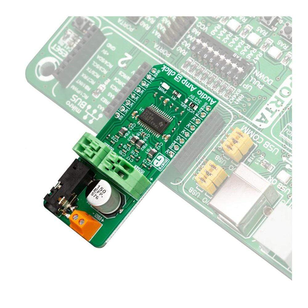
The AudioAmp 5 Click Board™ is supported by a mikroSDK compliant library, which includes functions that simplify software development. This Click Board™ comes as a fully tested product, ready to be used on a system equipped with the mikroBUS socket.
Downloads
The AudioAmp 5 Click Board™ requires an external Power Supply Unit (PSU) for its operation. It can use a wide range of power supply voltages, from 3.5V up to 14.4V. Audio Amp 5 click a perfect solution for different kinds of active desktop speakers, battery-powered Bluetooth® and wireless speakers, TV sets and PC monitors, and other types of consumer audio equipment. Due to its high efficiency, it can even be used as a sound reinforcement solution for various IoT applications.
How Does The AudioAmp 5 Click Board™ Work?
The main component of the AudioAmp 5 Click Board™ is the TPA3138D2, an inductorless stereo class-D audio amplifier, from Texas Instruments. It has many features which make this IC a very attractive solution for battery-powered and stand-alone active speakers. It is very flexible regarding the PSU voltage: it can work with voltages within the range from 3.5V to 14.4V. With only 3.5V at the PSU connector, it can still deliver 1W of power to 6Ω load (per channel). However, its nominal operating voltage is 12V, reaching up to 10W of power to the connected 6Ω speaker, with only 1% of Total Harmonic Distortion (THD).
.jpg)
The TPA3138D2 IC features a set of protections, including output short circuit, over-temperature, under-voltage, and over-voltage protection. If any of these protections are activated, they will be reported at the SD/FAULT (EN) I/O pin. The TPA3138D2 IC can also detect a constant DC current at the output. When a DC detection event occurs, the outputs are turned OFF, protecting the connected speakers that way. Very often, a DC detection event can be triggered when the circuit is powered up, so it is advisable to hold the EN pin to a LOW logic level for a short period, preventing faulty DC detection reports, as well as loud pops.
The output stage of the TPA3138D2 operates in Bridge-Tied Load (BTL) topology. This means that there are two outputs per channel: one inverted and one non-inverted (OUTN and OUTP). Class-D amplifier produces the sound by modulating the pulse-with of the output voltage. It offers a choice of two PWM modulation schemes, selectable by the MODE_SEL pin of the IC. This pin is routed to the mikroBUS™ RST pin, labeled as MDS on the AudioAmp 5 Click Board™. By default, MDS pin is pulled to a LOW logic level by a resistor.
When the MDS pin is set to a LOW logic level, the TPA3138D2 uses the BD Modulation scheme. This scheme reduces the need for a typical LC reconstruction filter at the output. While there is no input, both OUTN and OUTP are in phase, with 50% duty cycle. There is no current through the speaker, in this case. The duty cycle will increase at the OUTP and decrease at the OUTN at the same time, when the positive half-phase of the audio signal is applied at the input. For the negative half-phase at the input, the opposite will happen. The greater the difference in pulse width, the greater the current through the connected speaker.
When MDS pin is set to a HIGH logic level, the TPA3138D2 uses the 1SPW Modulation scheme. This scheme allows very low idle current and better overall efficiency, at the expense of somewhat increased THD. Both OUTP and OUTN are held in phase at about 15% duty cycle. As the input signal is applied, one output is driven to the GND, while the other output increases. The modulation takes place through this single output, reducing the switching losses. Again, the positive half-phase will cause the OUTN to be driven to GND, while the negative half-phase of the input signal causes the OUTP to be driven to GND.
The SD/FAULT pin allows the host MCU to enable/disable outputs. By pulling this pin to a LOW logic level, the outputs are muted and the TPA3138D2 IC enters the low-current state, reducing the supply current to the absolute minimum level. Muting the TPA3138D2 before cutting down the power supply reduces pops and clicks that might appear in this case. The SD/FAULT pin is routed to the mikroBUS™ CS pin labeled as EN on this Click board™, and it is pulled to a HIGH logic level by a resistor.
There is a selectable input gain on the AudioAmp 5 Click Board™. By applying a LOW logic level to the GAIN_SEL pin, the input gain is set to 20dB. A HIGH logic level sets the input gain to 26dB. This allows matching the input signal so that the optimal output level can be reached. This pin is routed to the mikroBUS™ PWM pin labeled as GS, and it is pulled to the LOW logic level by a resistor.
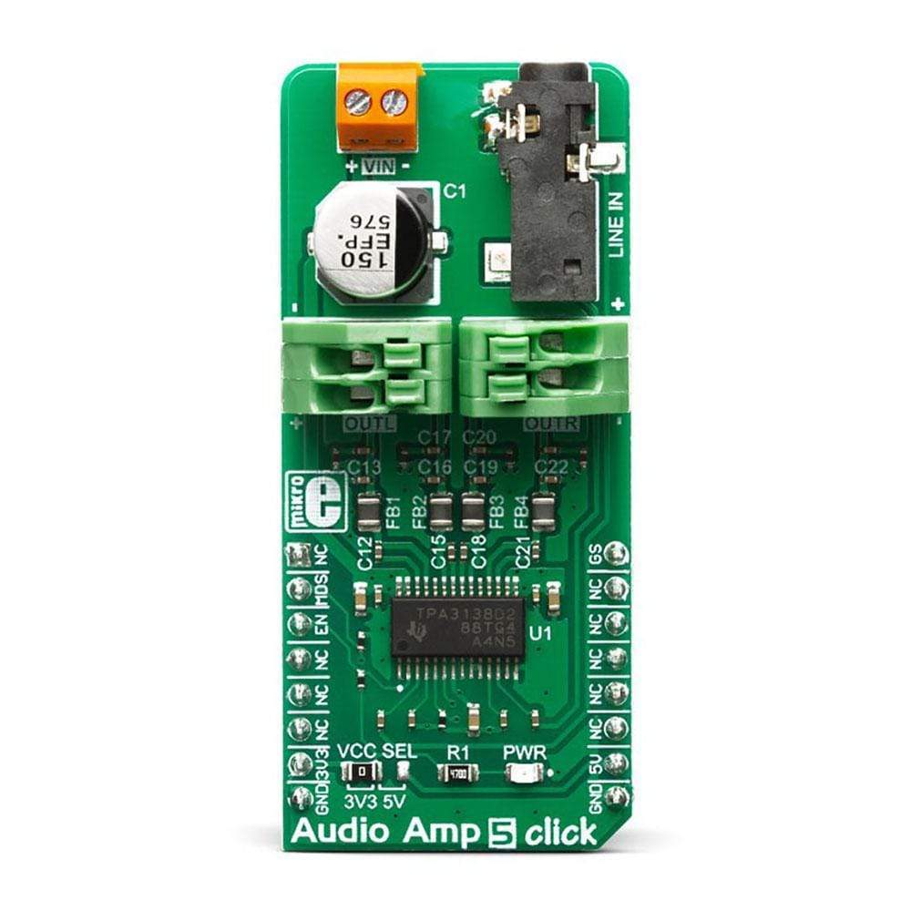
The external PSU should be connected to the VIN terminal. A line-level audio source can be connected to the LINE IN 3.5mm jack stereo connector, while the speakers should be connected to the angled spring-terminals, labeled as OUTL and OUTR. These terminals have their polarities marked on the top overlay.
Although the TPA3138D2 IC requires an external PSU, it still uses power from the mikroBUS™ for the logic levels of its control pins. There is a logic voltage level selection SMD jumper labeled as VCC SEL, which allows interfacing with both 3.3V and 5V-tolerant pins of the host MCU.
SPECIFICATIONS
| Type | Amplifier |
| Applications | A perfect solution for different kinds of active desktop speakers, battery-powered BT and wireless speakers, TV sets and PC monitors, and other types of consumer audio equipment. Due to its high efficiency, it can even be used as a sound reinforcement solution for various IoT applications. |
| On-board modules | TPA3138D2, an inductorless stereo class-D audio amplifier, from Texas Instruments |
| Key Features | High efficiency, low power dissipation with no extra heat-sinks required, a set of protection features for reliable operation, it can be operated with the wide range of voltages, etc. |
| Interface | GPIO |
| Compatibility | mikroBUS |
| Click board size | L (57.15 x 25.4 mm) |
| Input Voltage | 3.3V or 5V |
PINOUT DIAGRAM
This table shows how the pinout on the AudioAmp 5 Click Board™ corresponds to the pinout on the mikroBUS™ socket (the latter shown in the two middle columns).
| Notes | Pin | Pin | Notes | ||||
|---|---|---|---|---|---|---|---|
| NC | 1 | AN | PWM | 16 | GS | Gain Select | |
| Mode Selection | MDS | 2 | RST | INT | 15 | NC | |
| Chip Enable/Fault | EN | 3 | CS | RX | 14 | NC | |
| NC | 4 | SCK | TX | 13 | NC | ||
| NC | 5 | MISO | SCL | 12 | NC | ||
| NC | 6 | MOSI | SDA | 11 | NC | ||
| Power Supply | 3.3V | 7 | 3.3V | 5V | 10 | 5V | Power Supply |
| Ground | GND | 8 | GND | GND | 9 | GND | Ground |
ONBOARD SETTINGS AND INDICATORS
| Label | Name | Default | Description |
|---|---|---|---|
| PWR | PWR | - | Power LED indicator |
| JP1 | VCC SEL | Left | Logic voltage level selection: left position 3.3V, right position 5V |
| CN1 | LINE IN | - | 3.5mm stereo jack for audio input |
| OUTL | OUTL | - | Left speaker connector |
| OUTR | OUTR | - | Right speaker connector |
| VIN | VIN | - | External PSU connector |
2X30W AMP ELECTRICAL CHARACTERISTICS
| Description | Min | Typ | Max | Unit |
|---|---|---|---|---|
| External PSU Voltage | 3.5 | 14.4 | V | |
| Minimum load Impedance | 3.2 | Ω | ||
| Continuous output power | 10 | W | ||
| Total Harmonic Distortion (THD) at 10W; 6Ω; 10V | 1 | % | ||
| Signal-to-Noise Ratio (SNR) | 102 | dB |
| General Information | |
|---|---|
Part Number (SKU) |
MIKROE-3401
|
Manufacturer |
|
| Physical and Mechanical | |
Weight |
0.024 kg
|
| Other | |
EAN |
8606018714728
|
Frequently Asked Questions
Have a Question?
Be the first to ask a question about this.