


Mikroelektronika d.o.o.
4D-Display Click Board™
4D-Display Click Board™
SKU: MIKROE-3044
Couldn't load pickup availability

Overview
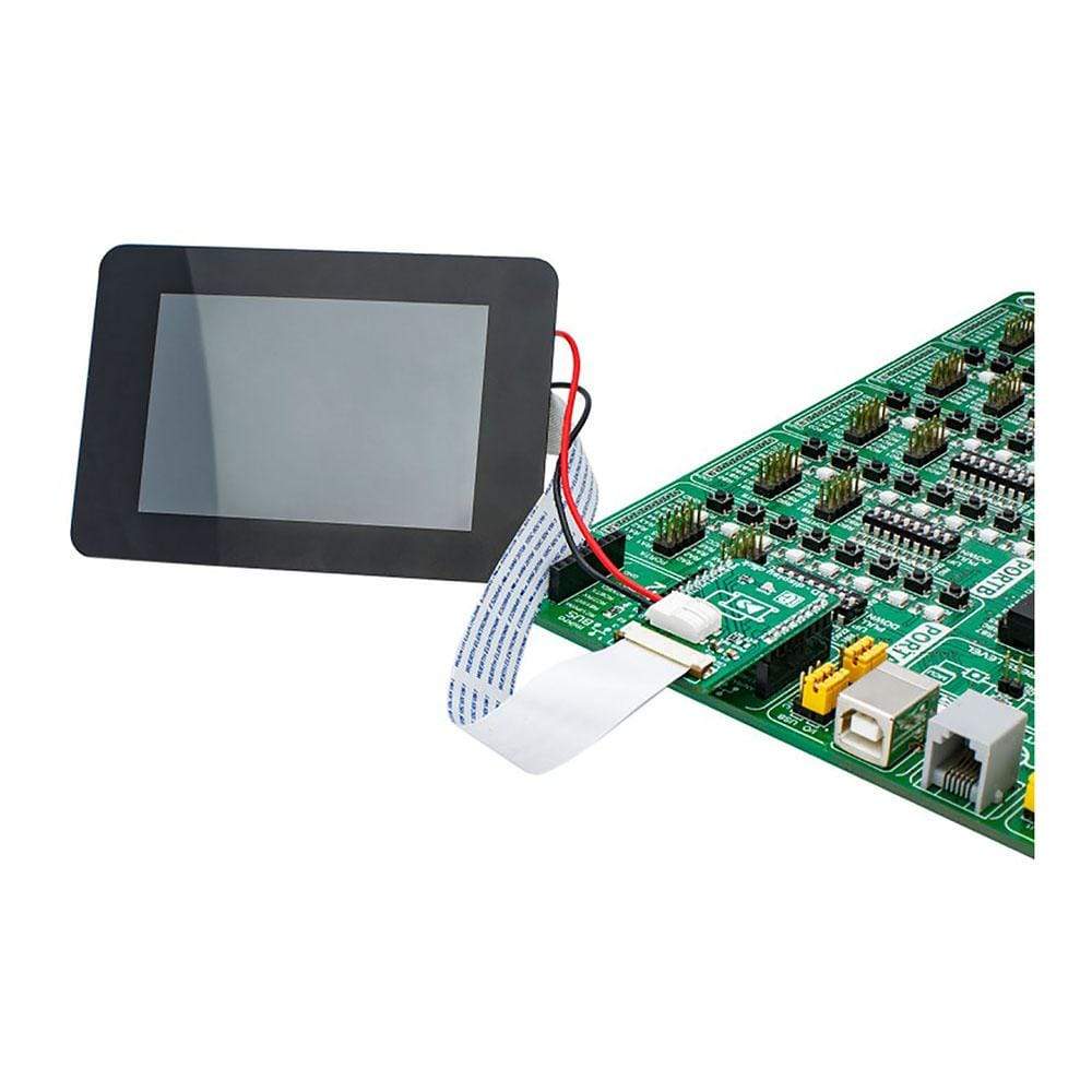
The 4D - Display Click Board™ is an adapter Click Board™ that offers a mikroBUS interface for controlling 4D Systems gen4 Series intelligent Display Modules. 4D Systems designs and manufactures a wide range of Intelligent Display Modules equipped with powerful graphics processors. Their displays allow graphical objects control by exchanging specifically formatted messages with the external microcontroller (MCU) over the UART.
By utilizing the 4D - Display Click Board™, it is possible to develop an MCU firmware application that can interact with the graphic objects on the 4D Intelligent Display Module over the mikroBUS. This significantly simplifies the application design, while reducing the processing load on the host MCU, allowing amazing graphically based applications to be created, even with slower 8-bit MCUs.
Downloads
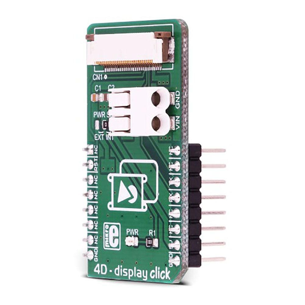
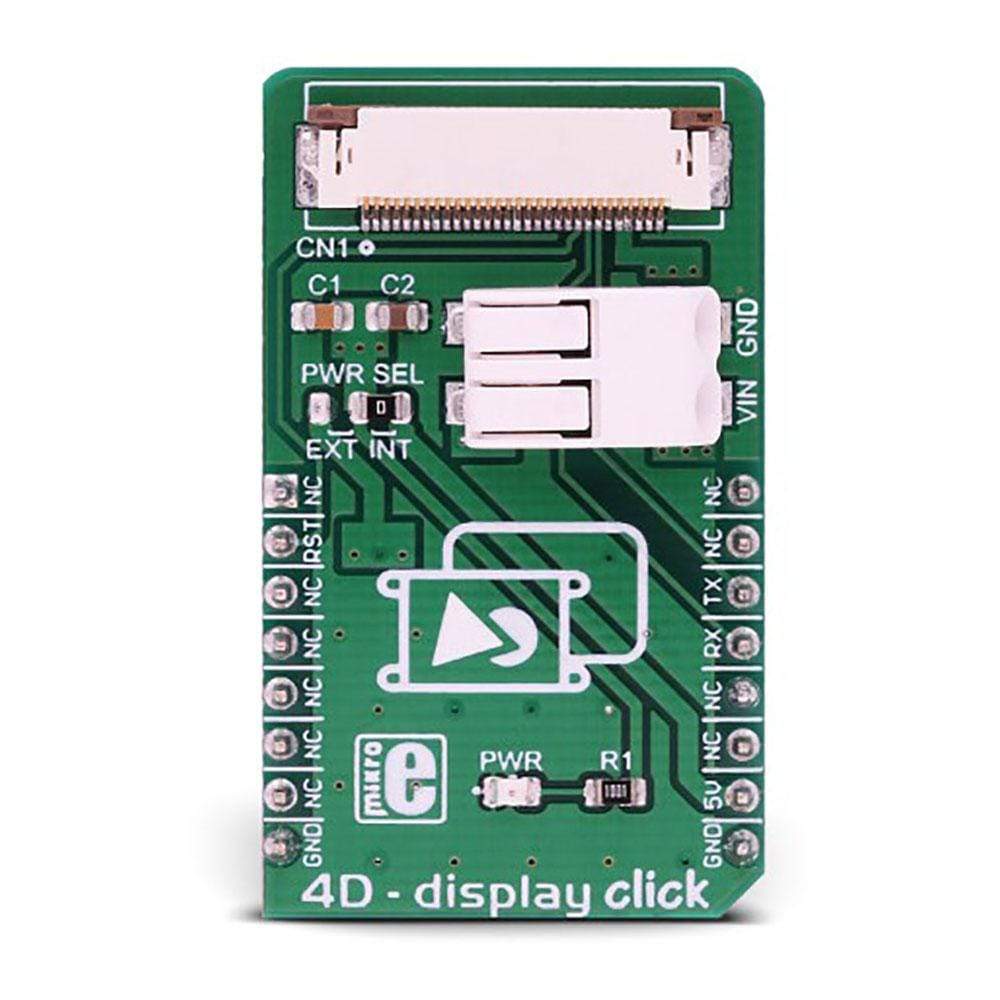
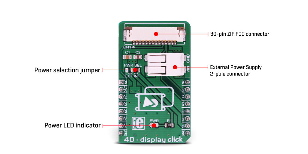
The 4D-Display Click Board™ offers a high quality 30-pin ZIF FFC connector for display connection, as well as a 2-pole SMD terminal block for connecting an external power supply, for cases when the connected display demands more power than the mikroBUS™ is able to provide. A small SMD jumper is used to select the external power supply source in this case. This Click board™ offers a reliable and fast UART connection between the 4D intelligent display and the development system, allowing any system equipped with the mikroBUS™ to harness the graphical power of the 4D intelligent display.
How Does The 4D-Display Click Board™ Work?
The 4D-Display Click Board™ is an adapter, used to interface gen4 intelligent display modules produced by, with the MCU systems equipped with the mikroBUS™ socket. The Click board™ is equipped with a high quality 30-pin ZIF FFC connector, which allows reliable and secure connection with the intelligent display module. The gen4 intelligent display modules are equipped with the powerful DIABLO 16 graphic processors from 4D Labs, which are used to accelerate graphic processing. The gen4 display module product family offers ZIF FFC connection interface, so these displays can be used with 4D - display click. By utilizing the proprietary software IDE called, it is possible to build accelerated graphic objects on these displays, each with its unique ID, type and value. This information can be exchanged with the smart display module over the UART. This is where the 4D-Display Click Board™ adapter comes in handy: by connecting the previously programmed intelligent display module to this Click board™, an interaction between the MCU running a custom firmware and the display itself is made possible.
For example, it is possible to read the ambient light data provided by the UV 4 click installed in the mikroBUS™ socket 2, while showing it on a gauge displayed at the screen of the intelligent display module, connected to the 4D - display click on the mikroBUS™ socket 1. By transmitting the UART data that contains the unique ID of the gauge object and the light intensity reading in the place of the value parameter, the intelligent display will automatically move the gauge scale to show the new updated value. Communication in the other direction is possible, too: touching a pre-programmed button can perform an action on the host MCU, which will receive the UART message from the smart display, containing the unique ID of the button object and its pressed state.
Besides the UART RX and TX lines, the RST pin is also routed to the ZIF FFC connector. This pin allows the host controller to reset the display if necessary. The Click board™ also contains a 2-pole SMD terminal block, which is used to connect an external power supply, if required by some of the more power-demanding displays. In this case, the small SMD jumper labelled as the PWR SEL should be moved to the EXT position. This will redirect the display module to use the externally connected power supply. The SMD terminal block allows AWG wire sizes between 18 to 24 to be used. It is very simple to use and establishes a reliable connection
More information about 4D intelligent display modules and the software IDE used to program them, can be found on the official site of the.
SPECIFICATIONS
PINOUT DIAGRAM
This table shows how the pinout of the 4D-Display Click Board™ corresponds to the pinout on the mikroBUS™ socket (the latter shown in the two middle columns).
| Notes | Pin | Pin | Notes | ||||
|---|---|---|---|---|---|---|---|
| NC | 1 | AN | PWM | 16 | NC | ||
| Reset | RST | 2 | RST | INT | 15 | NC | |
| NC | 3 | CS | RX | 14 | TX | UART TX | |
| NC | 4 | SCK | TX | 13 | RX | UART RX | |
| NC | 5 | MISO | SCL | 12 | NC | ||
| NC | 6 | MOSI | SDA | 11 | NC | ||
| NC | 7 | 3.3V | 5V | 10 | 5V | Power supply | |
| Ground | GND | 8 | GND | GND | 9 | GND | Ground |
ONBOARD SETTINGS AND INDICATORS
| Label | Name | Default | Description | |
|---|---|---|---|---|
| PWR | PWR | - | Power LED indicator | |
| PWR SEL | PWR SEL | Right | Power supply source selection: left position external power supply, right position 5V mikroBUS™ power rail | |
ONBOARD CONNECTORS
| Label | Name | Description |
|---|---|---|
| TB 1 | VIN, GND | External power supply input terminal |
| CN 1 | CN 1 | ZIF FFC for smart display connection |
| General Information | |
|---|---|
Part Number (SKU) |
MIKROE-3044
|
Manufacturer |
|
| Physical and Mechanical | |
Weight |
0.019 kg
|
| Other | |
EAN |
8606018713080
|
Frequently Asked Questions
Have a Question?
Be the first to ask a question about this.