


Mikroelektronika d.o.o.
Opto 2 Click Board™
Opto 2 Click Board™
SKU: MIKROE-3015
Couldn't load pickup availability


Overview
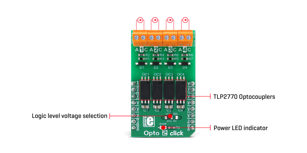
The Opto 2 Click Board™ is an optical isolator used to provide optical galvanic isolation of sensitive lines. The used optoisolation elements require a very low input current to be driven, down to 1.3mA (min). The speed of the internal optocoupler elements of the Opto 2 Click Board™ allows it to work with the signals up to 20MHz.
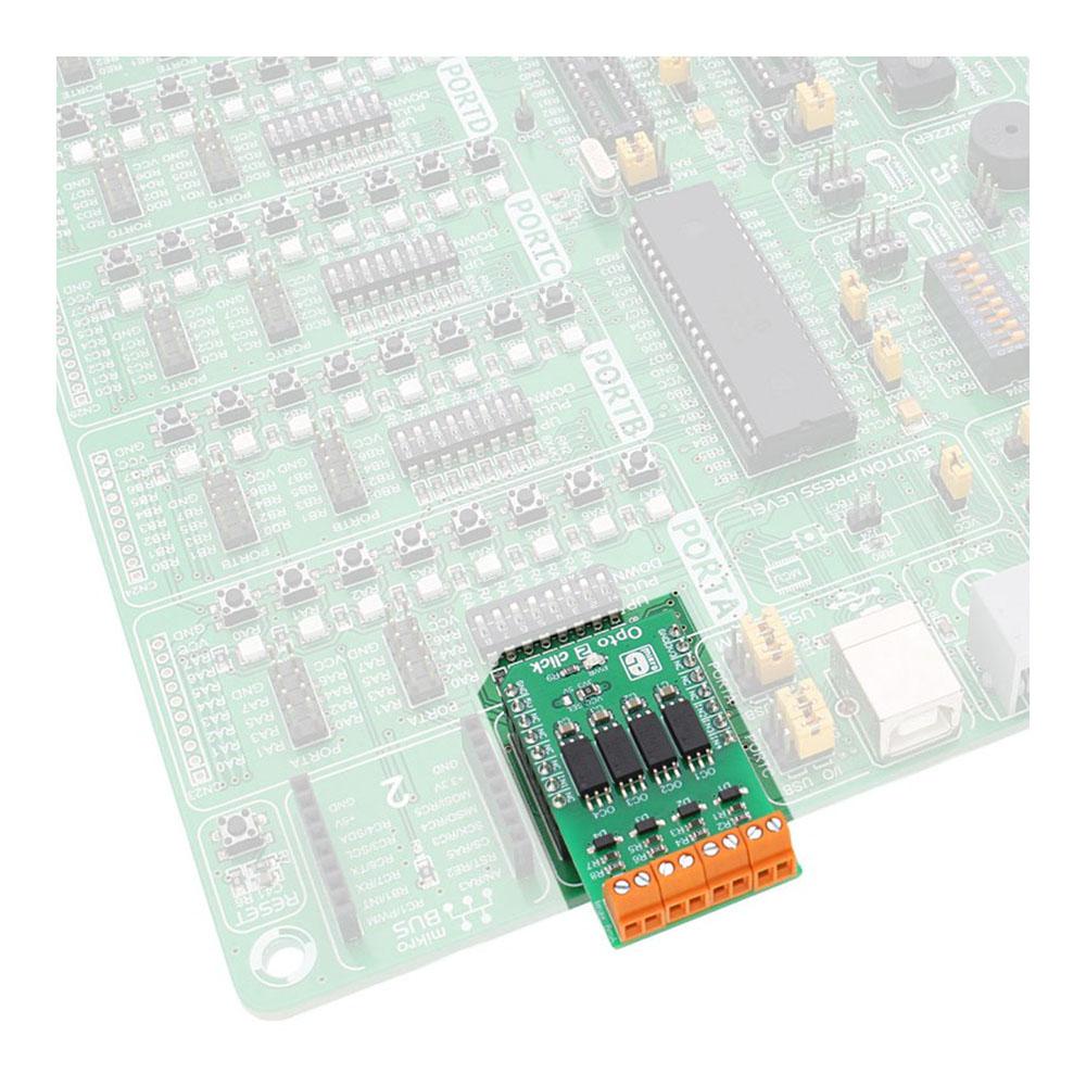
The Opto 2 Click Board™ can be used to provide galvanic isolation of the MCU pins, allowing driving by external components, while protecting it from surges up to 5kV on the driver side.
Downloads
The Opto 2 Click Board™ can be used in applications where the MCU input side is at risk of high voltage surges in a noisy environment. Since it provides galvanic isolation, the electrical potential of the input side circuit does not have to be the same as the electrical potential of the MCU circuit. Featuring reinforced galvanic isolation, the Opto 2 Click Board™ blocks so-called stray currents, that may appear as a result of differences in ground potential, or the electromagnetic induction. Opto 2 click provides means to drive inputs of the connected MCU with a wide range of external applications and signals.
How Does The Opto 2 Click Board™ Work?
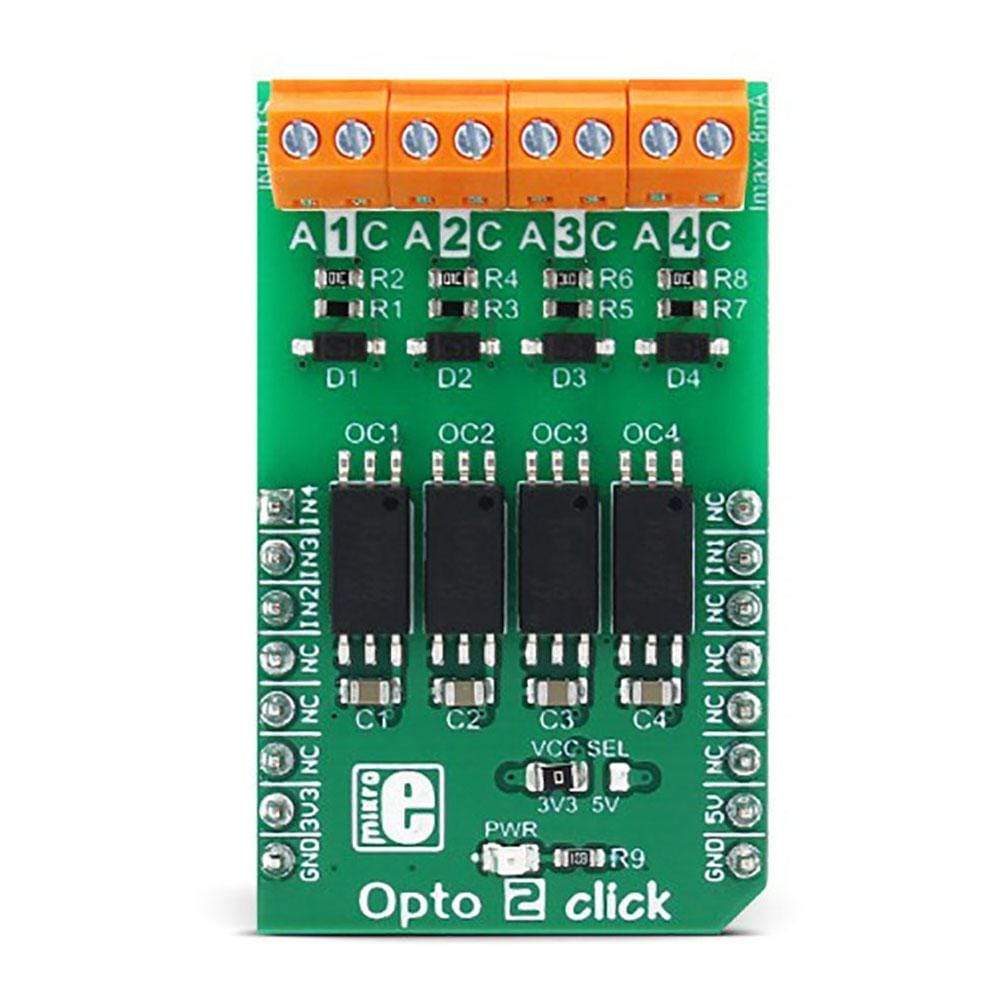
The Opto 2 Click Board™ uses four TLP2770, 20Mbps low-power optocouplers, from Toshiba. These are fast optocouplers, with their output stages shielded against EMI, allowing them to work at higher speeds, providing common-mode transient immunity of ±20 kV/μs. The internal LED elements are driven with 4mA for 5V operation or 2.6mA for 3.3V operation. The input stages are also equipped with (Schottky) diodes, which prevents inverse polarization of the LED elements and thus, permanent damage that might occur in that case.
The working principle of the optocouplers is quite simple: A photo-emitting element - usually a LED, is encapsulated inside the die along with the photo-sensitive element, which can be a photo-sensitive transistor or a photo-diode. LEDs and photo-sensing elements are galvanically isolated, making the input and output electrical networks completely independent of each other. When the LED is biased, it emits light which in return causes the current to flow through the photo-sensitive element. In these particular optocouplers, the output stage is additionally conditioned by a Schmitt trigger and it drives the output transistors which form a totem pole output stage. Having a totem pole output configuration allows the output stage to both sink and source current.
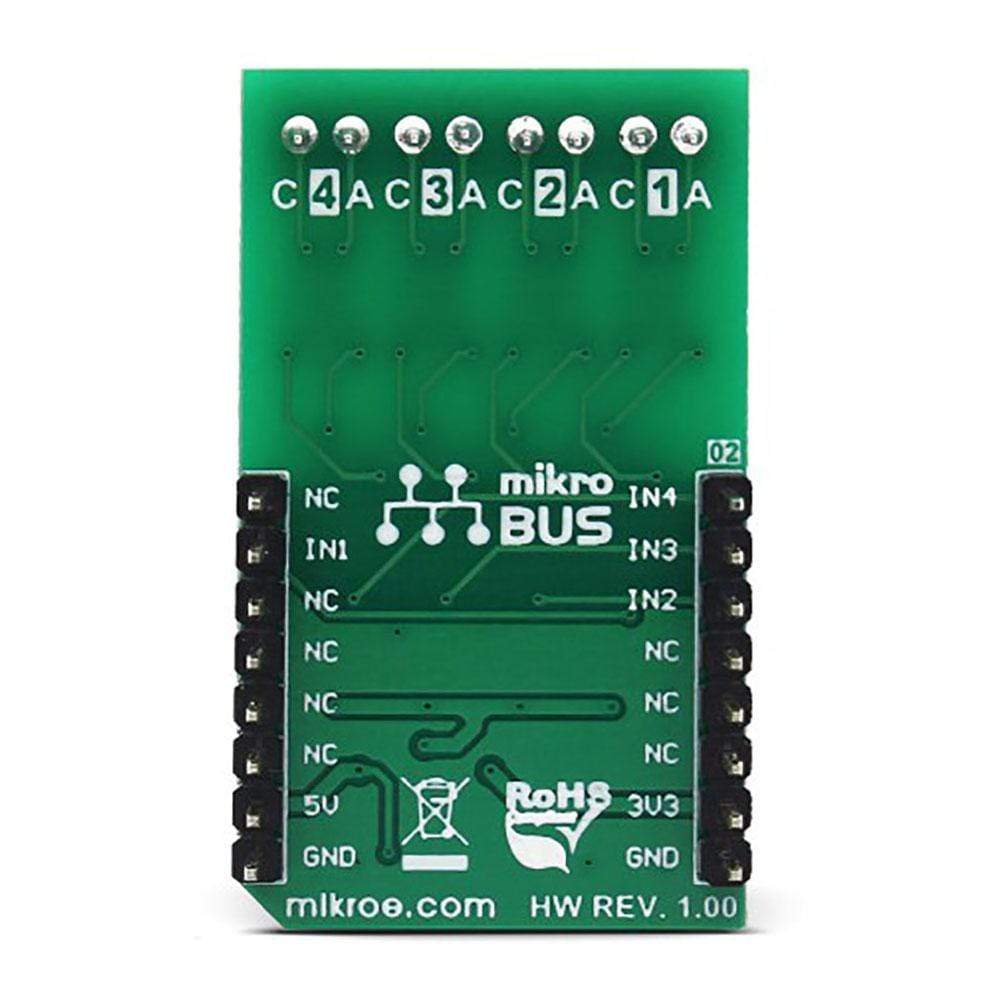
The optocoupler inputs - the anodes (labelled as A) and cathodes (labelled as C) of the internal optocoupler LEDs, are routed to the screw terminals, which allow connection to the external electrical circuit, used to trigger an event on the isolated MCU. The electrical potential between the anode and the cathode input of each optocoupler element should stay within the range between 3.3V and 5V.
The optocoupler outputs are routed to the mikroBUS™ The mikroBUS™ pins INT, CS, RST, and AN, are routed to the optocoupler outputs 1, 2, 3, and 4, respectively, and are labelled as IN1, IN2, IN3, and IN4. As already mentioned, the output stages are conditioned with the Schmitt trigger circuit, reducing the input noise sensitivity and false triggering. The Faraday shield protects the output stages against EMI and provides common-mode transient immunity of ±20 kV/μs. Although these mikroBUS™ pins are labelled as IN1 to IN4, they are actually output from the optocouplers, and it is highly recommended to use them as the INPUT pins on the host MCU.
The Opto 2 Click Board™ is equipped with an SMD jumper labelled as LOGIC, which allows selection of the voltage, applied to the optocoupler output stage. This voltage effectively determines the logic voltage level for the MCU pins. It can be selected between 3.3V and 5V, allowing this Click board™ to be interfaced with both 3.3V and 5V MCUs.
The provided library offers functions that simplify and speed up application development. The included example application demonstrates their use. This application can be used as a reference for custom projects.
SPECIFICATIONS
| Type | Isolators,Optocoupler |
| Applications | Used for isolation MCU input pins from the influence of the external circuitry, for interfacing an MCU with the electric circuit that works on a different potential |
| On-board modules | TLP2770, a 20-Mbps low-power optocoupler, from Toshiba. |
| Key Features | High isolation voltage of the galvanic barrier - up to 5kV, Faraday shield on the output stage, providing common-mode transient immunity of ±20 kV/μs, screw terminals for easy connection, low current consumption, high input sensitivity. |
| Interface | GPIO |
| Compatibility | mikroBUS |
| Click board size | M (42.9 x 25.4 mm) |
| Input Voltage | 3.3V or 5V |
PINOUT DIAGRAM
This table shows how the pinout on the Opto 2 Click Board™ corresponds to the pinout on the mikroBUS™ socket (the latter shown in the two middle columns).
| Notes | Pin | Pin | Notes | ||||
|---|---|---|---|---|---|---|---|
| Optocoupler 4 OUT | IN4 | 1 | AN | PWM | 16 | NC | |
| Optocoupler 3 OUT | IN3 | 2 | RST | INT | 15 | IN1 | Optocoupler 1 OUT |
| Optocoupler 2 OUT | IN2 | 3 | CS | RX | 14 | NC | |
| NC | 4 | SCK | TX | 13 | NC | ||
| NC | 5 | MISO | SCL | 12 | NC | ||
| NC | 6 | MOSI | SDA | 11 | NC | ||
| Power supply | +3.3V | 7 | 3.3V | 5V | 10 | +5V | Power supply |
| Ground | GND | 8 | GND | GND | 9 | GND | Ground |
ONBOARD SETTINGS AND INDICATORS
| Label | Name | Default | Description |
|---|---|---|---|
| LD1 | PWR | - | Power LED indicator |
| JP1 | LOGIC | Left | Logic voltage level selection: left position 3.3V, right position 5V |
OPTO 2 CLICK ELECTRICAL CHARACTERISTICS
| Description | Min | Typ | Max | Unit |
|---|---|---|---|---|
| Input forward current (I F ) | - | - | 8 | mA |
| Peak transient input forward current (I FPT ) | - | - | 1 | A |
| Output current (I O ) | - | - | 10 | mA |
| General Information | |
|---|---|
Part Number (SKU) |
MIKROE-3015
|
Manufacturer |
|
| Physical and Mechanical | |
Weight |
0.022 kg
|
| Other | |
EAN |
8606018712946
|
Frequently Asked Questions
Have a Question?
Be the first to ask a question about this.