


Mikroelektronika d.o.o.
GeoMagnetic Click Board™
GeoMagnetic Click Board™
SKU: MIKROE-2935
Couldn't load pickup availability


Overview
The GeoMagnetic Click Board™ is a digital magnetometric Click Board™ that can measure the geomagnetic field in three perpendicular axes. The onboard sensor uses FlipCore - a proprietary technology from Bosch, which results in a carefully tuned performance, tailored for demanding 3-axis mobile applications, such as a tilt-compensated electronic compass, gaming controllers, augmented reality applications and similar applications which require reliable and precise 3-axis magnetometric measurement.
Downloads
Three-axis Geomagnetic Sensor
The GeoMagnetic Click Board™ is a digital magnetometric board which can measure the geomagnetic field in three perpendicular axes. The on-board sensor uses FlipCore - a proprietary technology from Bosch, which results with a carefully tuned performance, tailored for demanding 3-axis mobile applications, such as a tilt-compensated electronic compass, gaming controllers, augmented reality applications and similar applications which require reliable and precise 3-axis magnetometric measurement.
Besides the magnetic field measurement functions, the GeoMagnetic Click Board™ also provides an advanced programmable interrupt engine, which allows for a flexible design and responsiveness of the application. The GeoMagnetic Click Board™ can use either SPI or I2C interface to communicate with the host controller. All these features make the GeoMagnetic Click Board™ an easy to use and reliable solution for a rapid development of geomagnetic based applications.
How Does it Work?
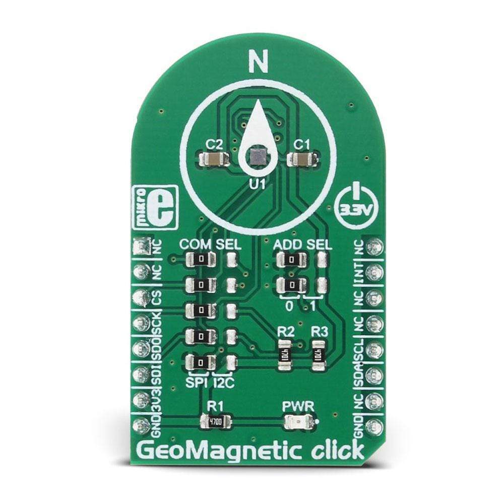
The GeoMagnetic Click Board™ carries the BMM150, a three-axis geomagnetic sensor from Bosh Sensortec. Featuring the proprietary FlipCore technology from Bosch, low-power consumption, and noise, as well as thermally compensated measurements, this device is specially tuned and tailored to be used in demanding 3-axis mobile applications.
The BMM150 module is able to work in four power modes: Power Off mode, Suspend mode, Sleep mode and Active mode. The overall power consumption is greatly affected by the selection of power modes. All modes except the Power Off mode can be set by programming the appropriate registers. Additionally, while working in Active mode, the power consumption depends on the measurement rate, which can be either timed with the programmed output data rate (Normal mode) or forced by the user (Forced mode).
The sensor output noise is processed by the internal integrator, so setting more measurement repetitions for the same axis will yield output results with less noise. This also affects the overall power consumption in the Active mode.
There are four interrupt engines available on this device: low threshold, high threshold and overflow and data ready (DRDY). Every interrupt engine can be enabled independently. If the interrupt is enabled, it will set the corresponding status bit in the status register. For this interrupt to appear on the INT pin of the BMM150 IC, a corresponding bit should be set in the configuration register. This pin is routed to the mikroBUS INT pin and can be used for triggering external events. Data ready pin is not physically available on the Click Board™, but still, its status bit can be read from the status register.
The temperature compensation is based on a hall plate sensor measurement. This IC outputs raw values for the measurements: DATAX, DATAY, DATAZ, and RHALL. The data width for the X and Y axes is different than the one for the Z and RHALL. DATAX and DATAY data fields are 13 bits wide, while DATAZ field is 15 bits wide. RHALL data field is 14 bits wide. The manufacturer recommendation is to read all the axes at once. The output registers are refreshed all at once after all the measurements are finished. While reading registers, a new measurement is not stored in the same registers, but buffered to shadow registers, instead. This prevents axes data mixing, so it is also recommended to read the whole register sequence in one burst. To further control the data reading sequence, two additional bits are used to indicate the data ready status and data overrun status.
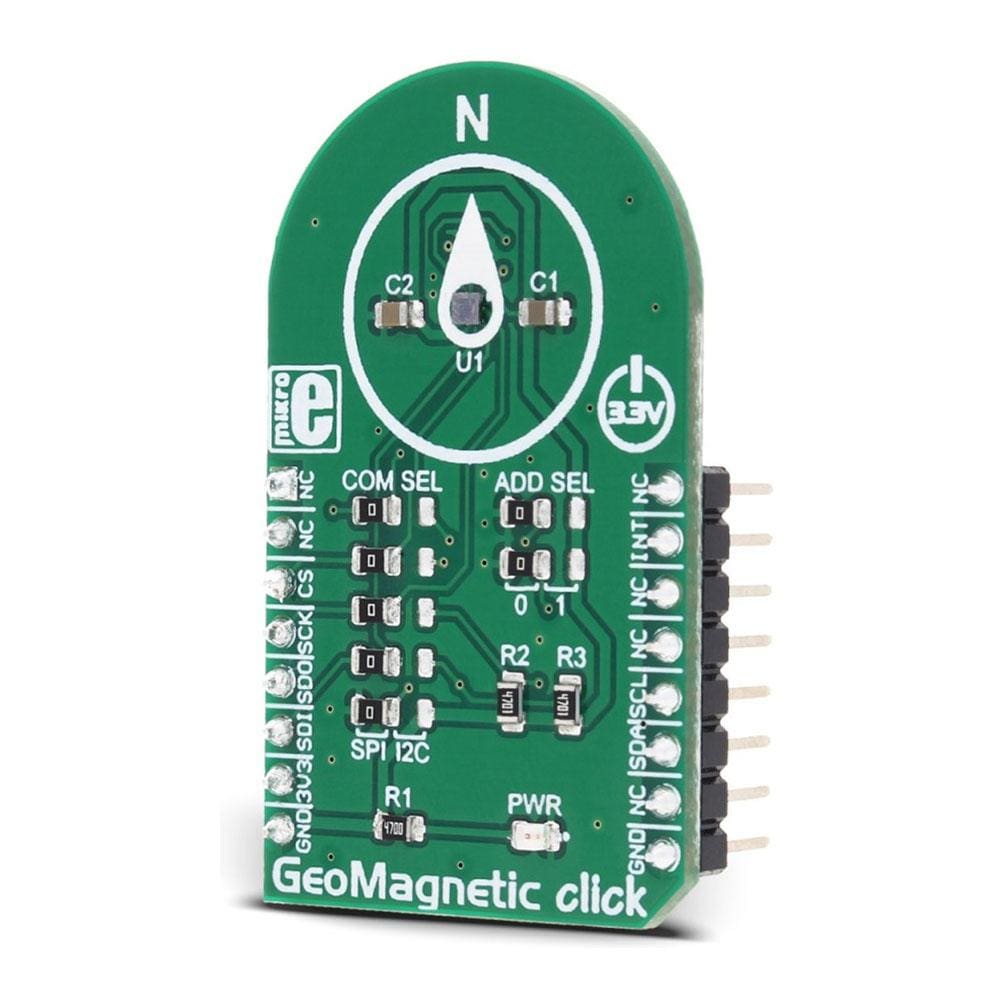
The GeoMagnetic Click Board™ can use either SPI or I2C communication interface. The selection between the interfaces can be done by switching the SMD jumper positions. There are two group of SMD jumpers. The first group is labelled as COM SEL and it is used to select the required interface type. It should be noted that all the jumpers need to be switched either left for SPI interface type or right for I2C interface type. Mixed positions are not allowed. The second group of SMD jumpers is labelled as ADD SEL and it is used to set the two least significant bits (LSB) of the I2C address. These jumpers are disregarded if the SPI interface is selected. More information about the registers and their settings can be found in the datasheet link, below.
The provided GeoMagnetic Click Board™ library offers simple and easy to use functions, which are demonstrated in the demo application. These functions allow easy and simple configuration management and data reading, speeding up the development process.
Specifications
| Type | Compass,Magnetic |
| Applications | The GeoMagnetic Click Board™ an easy to use and reliable solution for a rapid development of geomagnetic based applications |
| On-board modules | BMM150 geomagnetic sensor from Bosch |
| Key Features | Three-axis geomagnetic sensor |
| Interface | GPIO,I2C,SPI |
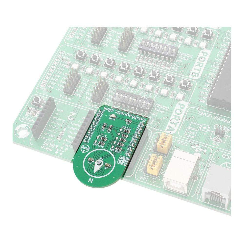
| Compatibility | mikroBUS |
| Click board size | M (42.9 x 25.4 mm) |
| Input Voltage | 3.3V |
Pinout Diagram
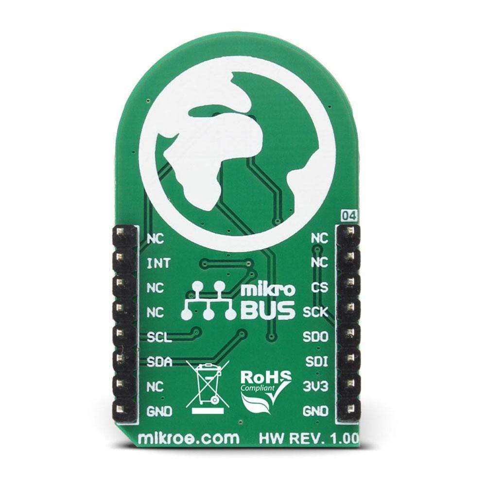
This table shows how the pinout on GeoMagnetic Click Board™ corresponds to the pinout on the mikroBUS™ socket (the latter shown in the two middle columns).
| Notes | Pin | Pin | Notes | ||||
|---|---|---|---|---|---|---|---|
| NC | 1 | AN | PWM | 16 | NC | ||
| NC | 2 | RST | INT | 15 | INT | Interrupt | |
| SPI Chip Select | CS | 3 | CS | RX | 14 | NC | |
| SPI Clock | SCK | 4 | SCK | TX | 13 | NC | |
| SPI Data OUT | SDO | 5 | MISO | SCL | 12 | SCL | I2C Clock |
| SPI Data IN | SDI | 6 | MOSI | SDA | 11 | SDA | I2C Data |
| Power supply | +3.3V | 7 | 3.3V | 5V | 10 | NC | |
| Ground | GND | 8 | GND | GND | 9 | GND | Ground |
GEOMAGNETIC CLICK SPECIFICATIONS
| Description | Min | Typ | Max | Unit |
|---|---|---|---|---|
| I2C Clock | 400 | kHz | ||
| SPI Clock (SDI, SDO load < 25pF) | 10 | MHz |
ONBOARD SETTINGS AND INDICATORS
| Label | Name | Default | Description |
|---|---|---|---|
| JP1 - JP5 | COM SEL | LEFT | Communication protocol selection: Left position - SPI, right position - I2C |
| JP6 - JP7 | ADD SEL | LEFT | I2C Address selection: Left position - 0, right position - 1 |
| LD1 | PWR | - | Power LED indicator |
| General Information | |
|---|---|
Part Number (SKU) |
MIKROE-2935
|
Manufacturer |
|
| Physical and Mechanical | |
Weight |
0.018 kg
|
| Other | |
EAN |
8606018712595
|
Frequently Asked Questions
Have a Question?
Be the first to ask a question about this.