
Mikroelektronika d.o.o.
RS485 3 Click Board™
RS485 3 Click Board™
SKU: MIKROE-2821
Couldn't load pickup availability


Overview
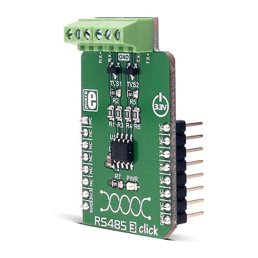
The RS485 3 Click Board™ uses SN65HVD31DR from Texas Instruments, a tri-state differential line driver and differential input line receiver. The Click Board™ is intended to be used as UART to RS-422/RS-485 communication interface. It is suited for transmitting smaller blocks of data over long distances, using the four-wire bus, allowing for full-duplex communication.
It can be used as a transceiver between the UART interface and RS-422/RS-485 communication bus. The RS485 3 Click Board™ can be used for controlling various building automation systems, lighting controllers, sensors and many small embedded devices that can all share the same bus, which can stretch up to 254 nodes and up to 1200m in length.
Downloads
The RS485 3 Click Board™ is an RS422/485 transceiver Click board™, which can be used as an interface between the TTL level UART and the RS422/485 communication bus. It features a full-duplex communication capability, bus Idle, open, and short-circuit detection, glitch free power-up and power-down for hot-plugging applications, driver current limiting, thermal shutdown, and more. It is well suited for transmitting data packets over long distances and noisy areas, using the four-wire bus, allowing for full-duplex communication. Internal ESD protection circuits protect the transceiver bus terminals against ±16-kV Human Body Model (HBM) electrostatic discharges.
Due to its robustness and reliability, the RS485 3 Click Board™ can be used in various applications that require reliable data transfer in various noisy environments, or over a substantial distance, when data rate transfer up to 5 Mbps is sufficient. RS485 3 click can be used for controlling various building automation systems, intelligent lighting systems (DMX), Point-of-Sale (POS) networks, and various other devices that need to establish a reliable communication over the RS422/485 bus, that can be up to 1500m in length.
How Does The RS485 3 Click Board™ Work?
The RS485 3 Click Board™ uses the SN65HVD31DR, a tristate differential line driver and differential input line receiver, from Texas Instruments. This click is intended to be used as a physical layer device, often referred to as PHY, providing physical interfacing of the MCU TTL level UART lines with the RS422/485 bus. It is well suited for transmitting smaller blocks of data over long distances, using two differential pairs, one for TX and other for RX line, allowing for full-duplex asynchronous communication. The SN65HVD31DR transceiver consists of a separate driver and receiver sections, which are always active upon powering the device. Driver section is used to drive the RS422/485 bus with the signal received on the UART RX line labeled as D on the IC, while the receiver section returns data from the bus back to the MCU via the UART TX line, labeled as R on the IC in the schematics.
.jpg)
RS422/485 standard only specifies electrical characteristics of the transmitter and the receiver. It does not specify or recommend any communications protocol, only the physical layer. The top layer communication protocol of choice can be used, such as the MODBUS or DMX protocols. Therefore RS485 3 click offers UART RX and TX pins, routed to the appropriate mikroBUS™ TX and RX UART pins. These pins are used by the MCU to send data to the RS485, in a form determined by the used protocol. Please note that RS485 3 click supports only 3.3V MCUs and it is not intended to be connected or controlled via the 5V MCU without a proper level shifting circuitry.
The SN65HVD31DR IC allows communication with data rates up to 5 Mbps. However, the maximal transfer speed is determined by the bus length: longer bus lines will result in less transfer speed. The RS422/RS485 bus needs to be terminated with the resistor on both ends, which is equal to the characteristic impedance of the used cable, in order to prevent line reflections. The RS485 standard prescribes using a twisted pair cable as the data bus. Twisted pair cable tends to cancel common-mode noise and causes cancellation of the magnetic fields generated by the current flowing through each wire, thereby reducing the effective inductance of the pair.
The RS-485 standard specifies that a compliant driver must be able to drive 32 unit loads (UL), where 1 unit load represents a load impedance of approximately 12 kΩ. Since the SN65HVD31 device is 1/8 UL, up to 256 such receivers can be supported by a single driver.
When used as the master, the driver section of the RS485 3 click is always active. The same is true for the slave receivers on this same signal pair. In the case when slaves need to communicate back to the master, they are using another pair and the slave device drivers have to be intermittently enabled and disabled so that only one driver on a slave is enabled at a time. Since the SN65HVD31 device does not contain RE and DE (Receiver Enable and Driver Enable) pins, slave driver cannot be disabled, resulting with bus contention, where the differential voltage can increase so that the resulting current can damage the IC. In that case, the driver current protection is activated, limiting this current to 250mA.
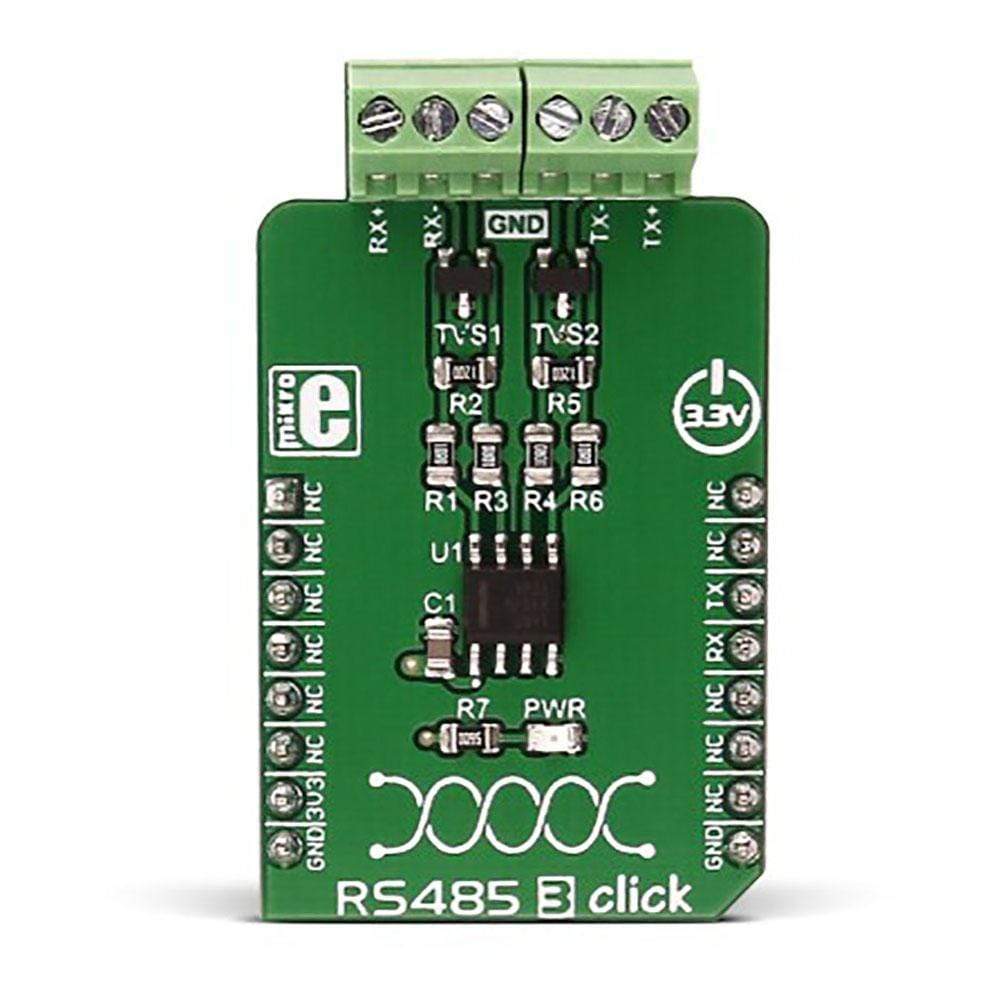
Differential inputs contain internal Schmitt trigger circuits, preventing uncertain states of the pins. This ensures that the outputs are always in a defined state, also providing noise immunity. To further improve the signal integrity, RS485 3 click is equipped with two transient voltage suppression diodes (TVS diodes) used to protect the circuit from transients that can occur on the RS422/485 bus.
There are two 2-pole screw terminals on board (RX+, Rx-, Tx+, Tx-) for connecting RS422/485 bus twisted pair cables, along with two screw terminals (GND) for common ground connection. The cables should be connected as close as possible to the termination resistors, preventing signal reflections in the parts of the signal cable that is not terminated by the resistor, so-called stubs.
MikroElektronika provides a library that contains functions compatible with the MikroElektronika compilers, which can be used for working with the RS485 3 Click. The library also contains an example application, which demonstrates their use. This example application can be used as a reference for custom designs.
SPECIFICATIONS
| Type | RS485 |
| Applications | Transceiver between UART interface and RS422/RS485 communication bus. Controlling various building automation systems, light controllers, sensors and small embedded devices that can all share the same bus. |
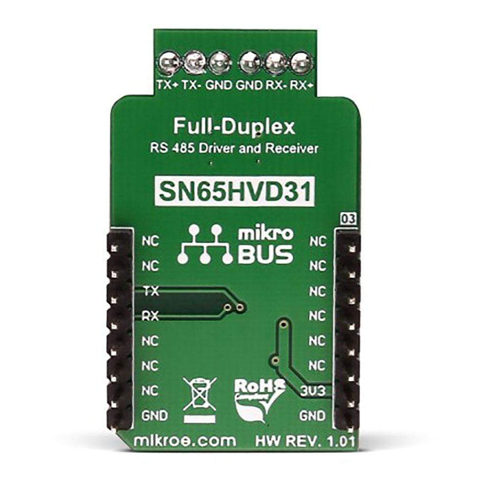
| On-board modules | SN65HVD31DR 3.3-V Full-Duplex RS-485 Driver and Receiver by Texas Instruments |
| Key Features | Full duplex four-wire serial communication over a distance up to 1200m, low power stand-by mode, receiver failsafe (detection of the short circuit or disconnection), hot plug capability |
| Interface | UART |
| Compatibility | mikroBUS |
| Click board size | M (42.9 x 25.4 mm) |
| Input Voltage | 3.3V |
PINOUT DIAGRAM
This table shows how the pinout on RS485 3 click corresponds to the pinout on the mikroBUS™ socket (the latter shown in the two middle columns).
| Notes | Pin | Pin | Notes | ||||
|---|---|---|---|---|---|---|---|
| NC | 1 | AN | PWM | 16 | NC | ||
| NC | 2 | RST | INT | 15 | NC | ||
| NC | 3 | CS | RX | 14 | TX | UART transmit data | |
| NC | 4 | SCK | TX | 13 | RX | UART receive data | |
| NC | 5 | MISO | SCL | 12 | NC | ||
| NC | 6 | MOSI | SDA | 11 | NC | ||
| Power supply | 3.3V | 7 | 3.3V | 5V | 10 | NC | |
| Ground | GND | 8 | GND | GND | 9 | GND | Ground |
RS485 3 CLICK ELECTRICAL SPECIFICATIONS
| Description | Min | Typ | Max | Unit |
|---|---|---|---|---|
| Bus common mode range | -7 | - | 12 | V |
| Output Short-Circuit Current | -250 | - | 250 | mA |
ONBOARD SETTINGS AND INDICATORS
| Label | Name | Default | Description |
|---|---|---|---|
| PWR | Power LED | - | Power LED indicates that the click is powered on |
| General Information | |
|---|---|
Part Number (SKU) |
MIKROE-2821
|
Manufacturer |
|
| Physical and Mechanical | |
Weight |
0.02 kg
|
| Other | |
EAN |
8606018711901
|
Frequently Asked Questions
Have a Question?
Be the first to ask a question about this.