


Mikroelektronika d.o.o.
DALI 2 Click Board™
DALI 2 Click Board™
SKU: MIKROE-2672
Couldn't load pickup availability


Key Features
Overview
The DALI 2 Click Board™ can be used to develop applications for controlling other slave nodes of the DALI network or to develop slave node applications that would respond to the commands sent by the master control unit.
The simplest DALI network consists of a controller and one or more slave devices, such as LED drivers, dimmers, and ballasts, equipped with DALI interfaces.
The DALI 2 Click Board™ offers a simple and reliable interface to DALI and DALI 2 communication buses, making it possible to dive into the world of intelligent lighting.
Downloads
DALI is an international standardized protocol for intelligent digital lighting control, that enables easy implementation of robust, scalable and flexible lighting networks. DALI stands for Digital Addressable Lighting Interface and it was first introduced in the late '90s. Since then, it has undergone a number of revisions. The most recent version of the DALI standard IEC 62386, is also known as DALI-2, which brings many new features to the existing DALI protocol.
The simplest DALI network consists of a controller and one or more slave devices, such as LED drivers, dimmers, and ballasts, equipped with DALI interfaces. The DALI 2 Click Board™ can be used to develop applications for controlling other slave nodes of the DALI network or to develop slave node applications that would respond to the commands sent by the master control unit. The DALI 2 Click Board™ offers a simple and reliable interface to DALI and DALI 2 communication buses, making it possible to dive into the world of intelligent lighting.
How Does The DALI 2 Click Board™ Work?
The master and the slave nodes are all connected to the DALI bus. The DALI bus consists of two wires, and offers a very flexible network routing topology: all nodes can be daisy-chained, connected in a star topology or any combination of these. DALI bus also requires a 24V, 250mA DALI compliant power supply unit to be connected to it, since DALI bus logic voltage levels range up to 24V. Also, the DALI standard strictly defines the maximum current through the bus, which should not exceed 250mA. The maximum current through each connected node is also defined and it should not exceed 2mA. DALI is not classified as SELV (Separated Extra Low Voltage) and therefore its wiring may be run next to mains cables or within multicore cables that include mains power.
Therefore, a DALI network cable is required to be mains-rated, with 600 V isolation and at least a 1 mm cross-section, with a maximum drop of 2 volts along the cable. That is roughly about 300m in length, depending on the specific resistance of the used cable.
The controller can monitor and control each slave device. The DALI protocol permits up to 64 nodes to be individually addressed, but it also allows multiple devices to be addressed simultaneously, via multicast and broadcast messages. DALI gateways can be used to further expand the network. The DALI bus communication data rate is 1200 bps (±10% max), and it consists of encoded data packets, exchanged between the master and slave nodes. The master sends 16bit Manchester encoded data packets, and the slave node responds back with an 8bit Manchester encoded data packet. The FORWARD FRAME is the frame sent by the master node and it consists of one START bit, eight address bits (slave address), eight data bits (command) and two STOP bits. The BACKWARD FRAME is the frame sent from the slave node back to the master. It consists of one START bit, eight data bits and two STOP bits.
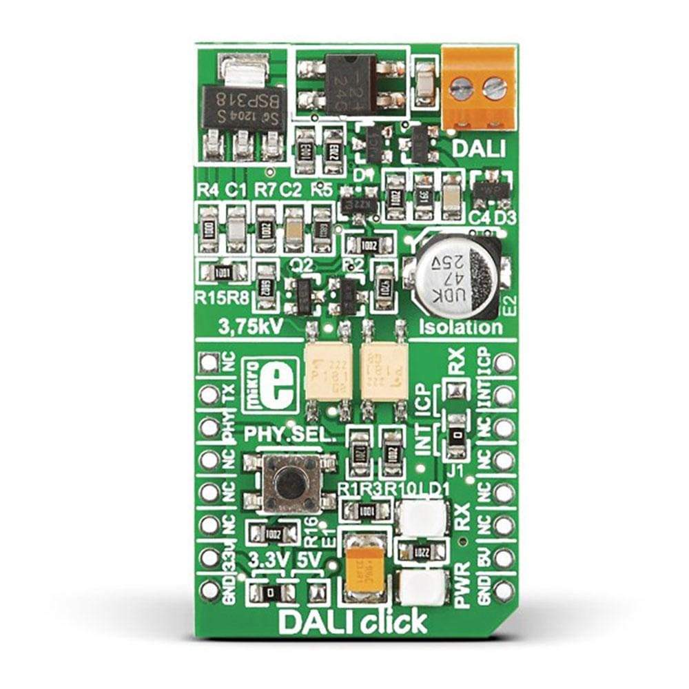
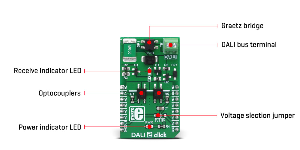
Signal levels are defined as 0 ± 6.5V for logic LOW or 0 (DALI bus active state) and 16 ± 6.5V for logic HIGH or 1 (DALI bus idle state). As per DALI standard, DALI 2 click board has a Graetz bridge rectifier on its DALI bus inputs, so a DALI bus can be connected to the DALI onboard screw terminal, disregarding the polarity of the signal. After it has been rectified, the DALI TX and RX signals go through the fast optocouplers and remain galvanically isolated from the rest of the circuit. These signals are routed to the RST and INT pins of the mikroBUS™ respectively, allowing the host MCU to exchange data via the DALI bus. There is an onboard SMD jumper, used to select the logic voltage level so that both 3.3V and 5V MCUs can be interfaced with this click board™. An onboard LED labelled as RX is used to indicate an incoming transmission from the DALI bus.
Although backward compatible, the DALI-2 standard introduces some new features, including 24bit frames, slightly changed logic voltage levels, standardization of different kinds of Control Gears (slave nodes), power supply through the BUS, more addressable nodes (up to 128), support for the LED colour fixtures, and so on. DALI 2 click is compliant with the DALI-2 physical layer requirements.
SPECIFICATIONS
| Type | DALI |
| Applications | The DALI 2 Click Board™ can be used for interfacing with the DALI network, but it is also compliant with the DALI-2 physical layer requirements. |
| On-board modules | Two EL357NC optocouplers |
| Key Features | The DALI 2 Click Board™ has been designed in cooperation with Microchip and it is compliant with the latest DALI standard revisions as well as the most recent DALI-2 version of this standard. |
| Interface | GPIO |
| Compatibility | mikroBUS |
| Click board size | M (42.9 x 25.4 mm) |
| Input Voltage | 3.3V or 5V |
PINOUT DIAGRAM
This table shows how the pinout on the DALI 2 Click Board™ corresponds to the pinout on the mikroBUS™ socket (the latter shown in the two middle columns).
| Notes | Pin | Pin | Notes | ||||
|---|---|---|---|---|---|---|---|
| NC | 1 | AN | PWM | 16 | NC | ||
| DALI TX | TX | 2 | RST | INT | 15 | RX | DALI RX |
| NC | 3 | CS | RX | 14 | NC | ||
| NC | 4 | SCK | TX | 13 | NC | ||
| NC | 5 | MISO | SCL | 12 | NC | ||
| NC | 6 | MOSI | SDA | 11 | NC | ||
| Power supply | +3.3V | 7 | 3.3V | 5V | 10 | +5V | Power supply |
| Ground | GND | 8 | GND | GND | 9 | GND | Ground |
DALI 2 CLICK ELECTRICAL SPECIFICATIONS
| Description | Min | Typ | Max | Unit |
|---|---|---|---|---|
| DALI bus current consumption | 1.6 | 2 | mA | |
| DALI bus allowed voltage | 0 | 24 | V |
ONBOARD SETTINGS AND INDICATORS
| Label | Name | Default | Description |
|---|---|---|---|
| LD1 | PWR | - |
Power LED indicator |
| LD2 | RX | - | Recieve indicator |
| JP2 | SEL JMP | Left | Power supply voltage selection, left position 3.3V, right 5V |
| General Information | |
|---|---|
Part Number (SKU) |
MIKROE-2672
|
Manufacturer |
|
| Physical and Mechanical | |
Weight |
0.021 kg
|
| Other | |
EAN |
8606018712472
|
Frequently Asked Questions
Have a Question?
Be the first to ask a question about this.