


Mikroelektronika d.o.o.
MCP2517FD Click Board™
MCP2517FD Click Board™
SKU: MIKROE-2379
Couldn't load pickup availability
Key Features
Overview
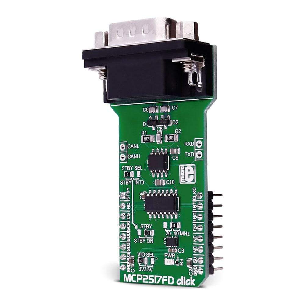
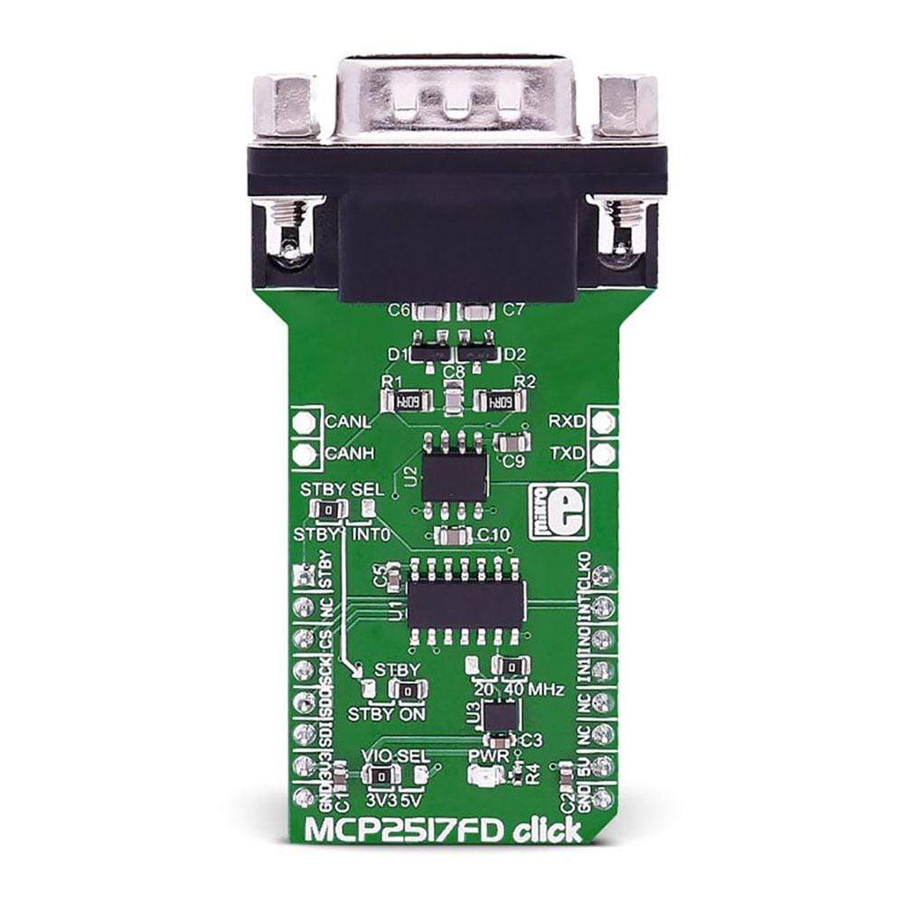
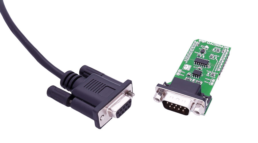
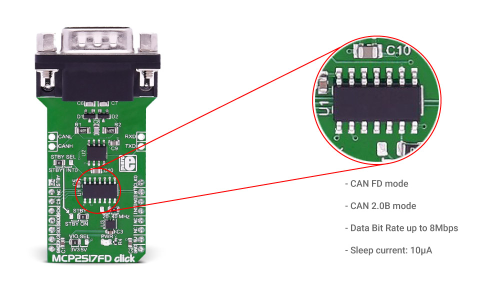
The MCP2517FD Click Board™ is a complete CAN solution that carries the MCP2517FD CAN FD controller and ATA6563 high-speed CAN transceiver from Microchip and a DB9 9-pin connector.
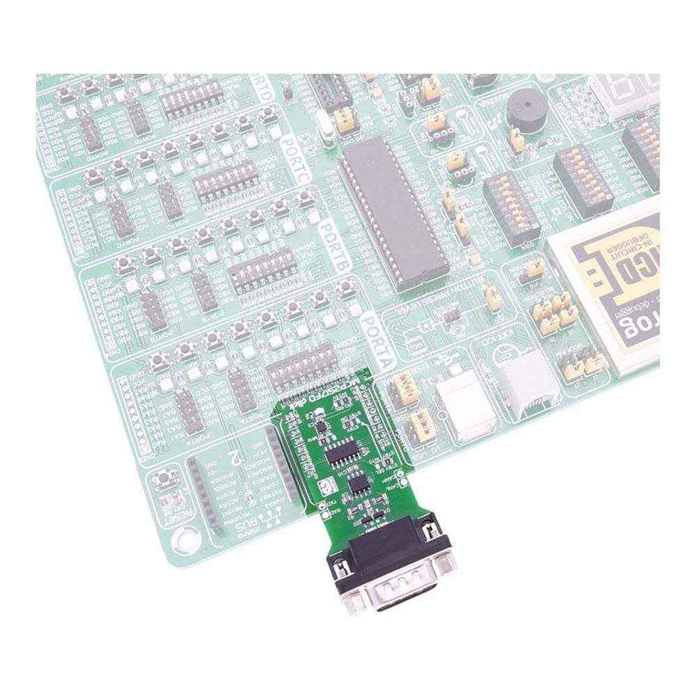
The MCP2517FD Click Board™ Click Board™ requires both 3.3V and 5V power supply. It communicates with the target microcontroller through the SPI interface, with additional functionality provided by the following pins on the MikroBUS socket: AN, PWM, INT, TX and RX.
Downloads
The MCP2517FD Click Board™ is a complete CAN solution which carries the MCP2517FD CAN FD controller and ATA6563 high-speed CAN transceiver from Microchip, as well as a DB9 9-pin connector.
The click requires both 3.3V and 5V power supply. It communicates with the target microcontroller through the SPI interface, with additional functionality provided by the following pins on the mikroBUS™ socket: AN, PWM, INT, TX and RX.
Note: For selecting the interface voltage level, use the onboard jumper, and choose between the 3.3V and 5V. For more information, see the Jumpers and Settings table below.
MCP2517FD Features
The MCP2517FD is a cost-effective and small-footprint CAN FD controller that can be easily connected to a microcontroller over an SPI interface. Therefore, a CAN FD channel can be easily added to a microcontroller that is either lacking a CAN FD peripheral, or that doesn't have enough CAN FD channels.
The MCP2517FD supports both, CAN frames in the Classical format (CAN2.0B) and CAN Flexible Data Rate (CAN FD) format.
ATA6563 CAN TRANSCEIVER FEATURES
ATA6563 is a high-speed CAN transceiver that provides an interface between a controller area network (CAN) protocol controller and the physical two-wire CAN bus.
The transceiver is designed for high-speed ( up to 5Mbit/s ) CAN applications in the automotive industry, providing differential transmit and receive capability.
It offers improved electromagnetic compatibility (EMC) and electrostatic discharge (ESD) performance.
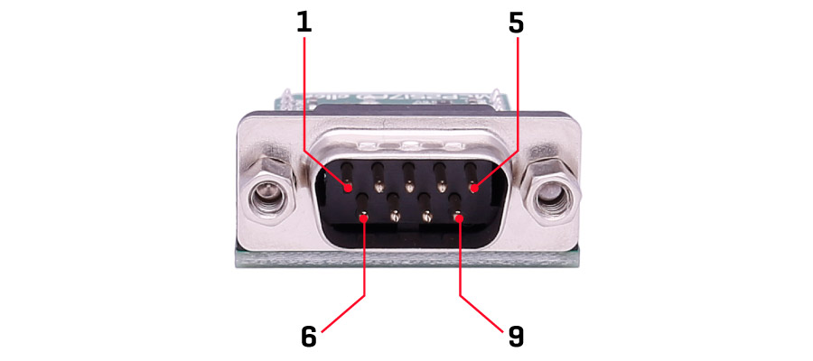
CONNECTOR FEATURES
This is a standard DB 9-pin male connector.
SPECIFICATIONS
| Type | CAN |
| Applications | Simple solution for adding CAN FD connectivity to your device |
| On-board modules | 9-pin CAN connector, ATA6563 CAN transceiver |
| Key Features | Communication speed up to 5Mbit/s, low electromagnetic emission (EME) and high electromagnetic immunity (EMI) |
| Interface | SPI |
| Compatibility | mikroBUS |
| Click board size | L (57.15 x 25.4 mm) |
| Input Voltage | 3.3V or 5V |
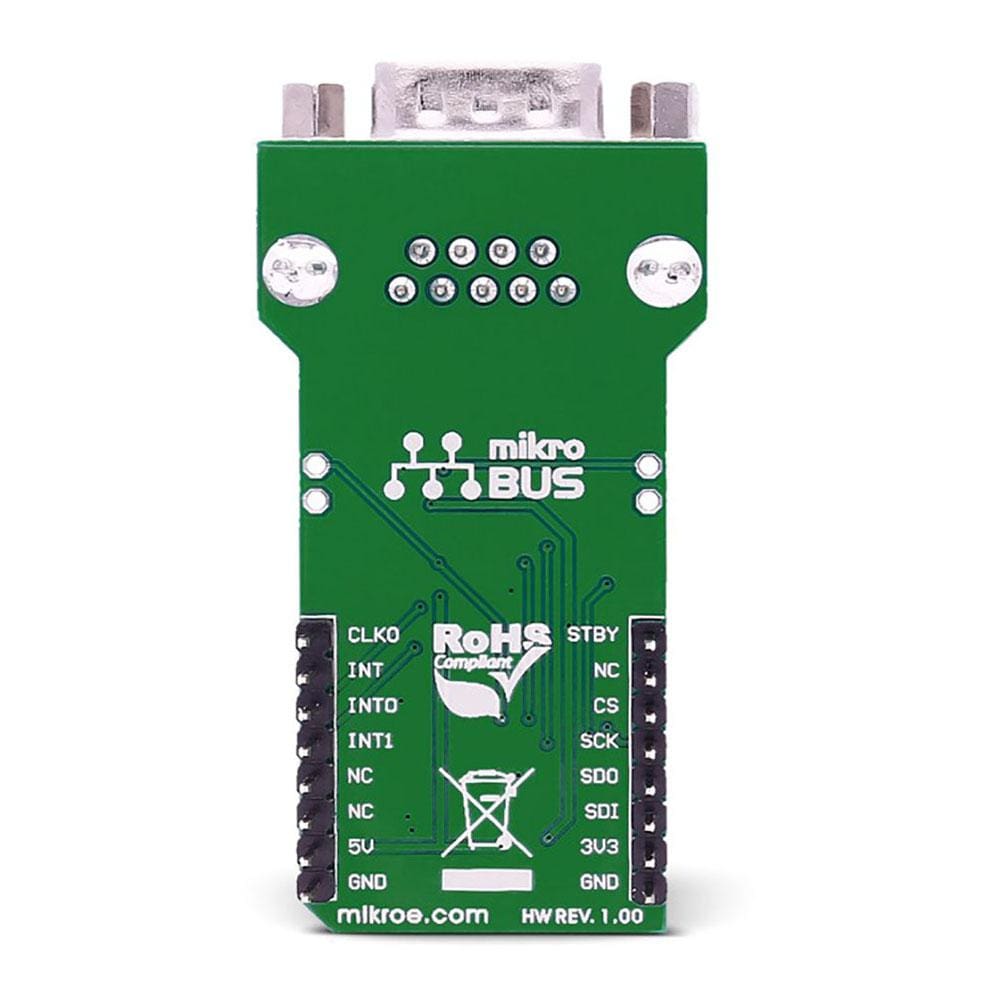
PINOUT DIAGRAM
This table shows how the pinout on MCP2517FD click corresponds to the pinout on the mikroBUS™ socket (the latter shown in the two middle columns).
| Notes | Pin | Pin | Notes | ||||
|---|---|---|---|---|---|---|---|
| Standby control IP | STBY | 1 | AN | PWM | 16 | CLKO | Clock OP |
| NC | 2 | RST | INT | 15 | INT | Interrupt OP | |
| Chip select | CS | 3 | CS | TX | 14 | INT0 | Int/GPIO 0 / ATA6563 StdBy |
| SPI Clock | SCK | 4 | SCK | RX | 13 | INT1 | Int/GPIO 1 |
| SPI data OP | MISO | 5 | MISO | SCL | 12 | NC | |
| SPI data IP | MOSI | 6 | MOSI | SDA | 11 | NC | |
| Power supply | +3.3V | 7 | 3.3V | 5V | 10 | +5V | Power supply |
| Ground | GND | 8 | GND | GND | 9 | GND | Ground |
ADDITIONAL PINS
| Name | I/O | Description |
|---|---|---|
| TX_CAN | I | CAN transmit |
| RX_CAN | O | CAN receive |
| CANL | I/O | CAN low line |
| CANH | I/O | CAN high line |
JUMPERS AND SETTINGS
| Designator | Name | Default Position | Default Option | Description |
|---|---|---|---|---|
| JP1 | VIO.SEL. | Left | 3V3 | Power Supply Voltage Selection 3V3/5V, left position 3V3, right position 5V |
| JP2 | STBY | Right | ON | Select Stand by function, default ON, other takes the STBY SEL configuration |
| JP3 | STBY SEL | Left | STBY | Takes STBY input from STBY pin or INT0 pin on mikroBUS™ |
| JP4 | Right | 40MHz | Selects between 20 and 40 MHz clock |
LEDS AND BUTTONS
| Designator | Name | Type | Description |
|---|---|---|---|
| CN1 | CONNECTOR | DB9 connector for CAN |
| General Information | |
|---|---|
Part Number (SKU) |
MIKROE-2379
|
Manufacturer |
|
| Physical and Mechanical | |
Weight |
0.028 kg
|
| Other | |
EAN |
8606018710447
|
Frequently Asked Questions
Have a Question?
Be the first to ask a question about this.