


Mikroelektronika d.o.o.
MCP2542 Click Board™
MCP2542 Click Board™
SKU: MIKROE-2299
Couldn't load pickup availability
Overview
The MCP2542 Click Board™ is the CAN bus transceiver, which allows TTL/CMOS level signals typically found on MCUs, to be used for the communication via the CAN bus, which uses the higher voltage levels and differential signals. In addition, this Click Board™ protects the sensitive MCU part of the device from excessive voltage spikes and electrostatic discharges (ESD), typically observed in automotive systems, where CAN communication is extensively used.
The MCP2542 Click Board™ uses the MCP2542WFD, a CAN FD transceiver, which offers a robust CAN bus interface, with ESD protection up to 13 kV, permanent dominant detection on TXD and CAN bus, battery short circuit and electrical transients suppression on the CAN bus, thermal protection, and more.
Downloads
The MCP2542 Click Board™ is the CAN bus transceiver, which allows TTL/CMOS level signals typically found on MCUs, to be used for the communication via the CAN bus, which uses the higher voltage levels and differential signals. In addition, the MCP2542 Click Board™ protects the sensitive MCU part of the device from excessive voltage spikes and electrostatic discharges (ESD), typically observed in automotive systems, where the CAN communication is extensively used. This Click board™ uses the MCP2542WFD, a CAN FD transceiver, which offers robust CAN bus interface, with ESD protection up to ±13 kV, permanent dominant detection on TXD and CAN bus, battery short circuit and electrical transients suppression on the CAN bus, thermal protection, and more.
These features make the MCP2542 Click Board™ an ideal solution for building high speed embedded CAN applications, which are reliable and well protected against rough conditions found in automotive electronic circuits. The onboard DE9 connector allows direct connection to most of the CAN systems, used by different manufacturers, reducing the application development time. It can be used for development of both automotive diagnostic applications, or custom vehicle gauges, panels, and similar additions, interfacing it directly to electronic automotive subsystems.
How Does The MCP2542 Click Board™ Work?
the MCP2542 Click Board™ uses the MCP2542WFD, a CAN FD transceiver IC with Wake-Up Pattern (WUP) option, from Microchip. This IC supports both CAN and recently established CAN FD protocols with up to 8Mbps. The communication through the CAN bus is differential and it is performed through the twisted pairs with the characteristic impedance of 120 Ω. The differential lines are driven by the CANH and CANL drivers, integrated on the MCP2542WFD IC. This provides robustness and immunity to electromagnetic interferences, typically observed in automotive systems. The ISO 11898 standard defines a signal line of twisted-pair cable as the network topology, terminated by the resistors with the characteristic impedance of the CAN bus (120 Ω), at both ends of the bus - in order to prevent signal reflection. This Click board™ does not need a termination resistor and includes additional protection on the CAN bus.
The CAN bus used two states: dominant and recessive. The dominant state is when the differential voltage between the CANH and CANL bus lines is above the dominant state detection level (0.9V), while the recessive state is below the recessive state detection level (0.5V). Allowed differential voltage on the CAN bus can range between -12V and 12V. CANH and CANL drivers are controlled by the logic level on the TX pin. HIGH logic level on the TX line results with the recessive state on the CAN bus, while LOW logic level results with the dominant state on the CAN bus. TXD line has the internal pull-up resistor (HIGH), making the MCP2542WFD device stay in recessive mode if the pin is left floating.
The CAN bus states are reflected on the RX pin: the dominant state will result in driving the RX pin to a LOW logic level, while the recessive state drives it to a HIGH logic level. This pin is also connected to the power supply via the internal pull-up resistor.
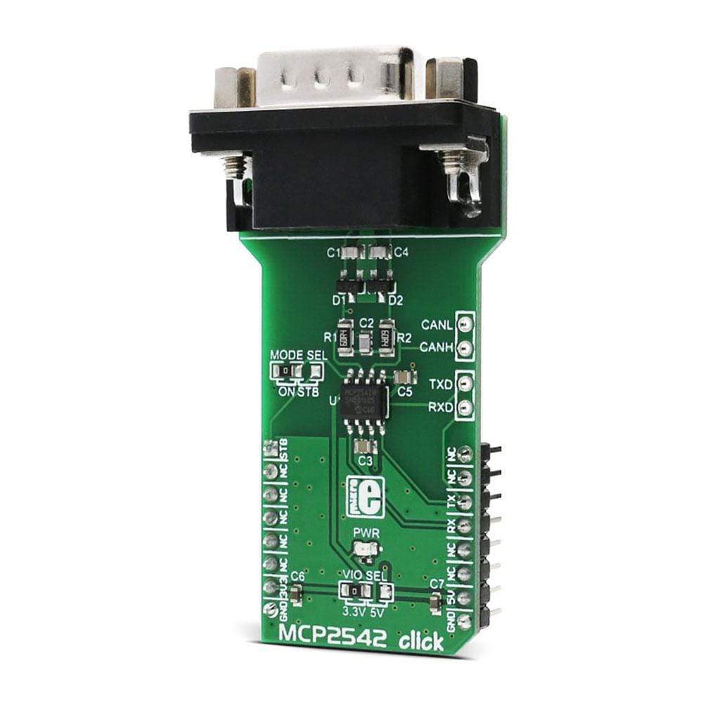
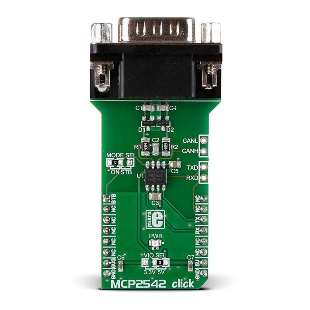
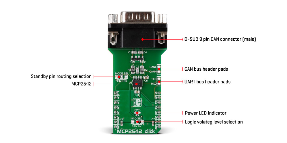
TX and RX lines of the MCP2542WFD are routed to the respective mikroBUS™ RX and TX pins, allowing MCU to drive CAN bus via UART. These lines are also routed to the header on the side of the Click board™, allowing them to be used with some other device. Besides TX and RX lines, CANH and CANL bus lines are also routed to a header, next to the RX and TX header. Finally, there is a D-SUB 9 male connector on the Click board™, which is used to connect to a CAN bus, directly. Logic level used for TX and RX lines is determined by the onboard SMD jumper, labelled as VIO SEL. It allows both 3.3V and 5V MCUs to be interfaced with this Click board™, determining the levels of the logic signals by the VIO pin of the MCP2542WFD. However, the power supply for the MCP2542WFD IC is taken directly from the mikroBUS™ 5V power rail.
The dominant/recessive states on the CAN bus are used for the message priority arbitration: the node which transmits signal with the higher priority (the lower the binary message identifier number, the higher the priority) will win the arbitration, and the node with the lower priority will abort the transmission, waiting for the bus to become available again. More detailed information about the CAN communication in general can be found in the link below.
Holding the TX pin to a LOW level for longer periods may result in blocking the traffic on the CAN bus since the dominant state overrides recessive states from other nodes on the bus (priority arbitration). This is avoided by employing the permanent dominant detection algorithm, which detects if the TX line is held LOW for too long. If so, the CANH and CANL drivers are disabled until the TX line state becomes HIGH. The receiver continues to work during this event.
The MCP2542WFD supports the Standby mode. While in Standby mode, high power consumption sections are powered off and only low-power part of the receiver is active, expecting the WUP (ISO11898-2 compliant Wake-Up Pattern) on the bus to resume the normal operation. The device can be set to the Standby mode by driving the STBY pin to a HIGH logic level. This pin is routed to the SMD jumper labelled as MODE SEL: if this jumper is set to STB position, the STBY pin will be routed to the mikroBUS™ AN pin, allowing MCU to control it. If the jumper is set to ON position, it will be routed to the GND directly, not allowing the MCP2542WFD device to enter the Standby mode.
SPECIFICATIONS
| Type | CAN,CAN FD |
| Applications | The MCP2542 Click Board™ can be used for development of both automotive diagnostic applications, or custom vehicle gauges, panels, and similar additions, interfacing it directly to electronic automotive subsystems. |
| On-board modules | MCP2542WFD, a CAN FD transceiver IC with Wake-Up Pattern (WUP) option, from Microchip |
| Key Features | High speed CAN/CAN FD interface with data rate up to 8 Mbps, ESD protection up to ±13 kV, permanent dominant detection on TXD and CAN bus, battery short circuit and electrical transients suppression on the CAN bus, thermal protection, and more. |
| Interface | UART |
| Compatibility | mikroBUS |
| Click board size | L (57.15 x 25.4 mm) |
| Input Voltage | 3.3V or 5V |
PINOUT DIAGRAM
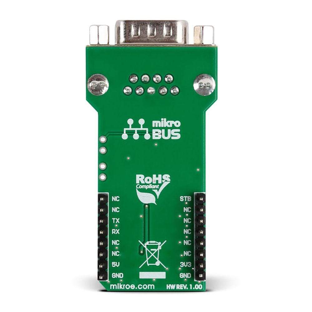
This table shows how the pinout of the MCP2542 Click Board™ corresponds to the pinout on the mikroBUS™ socket (the latter shown in the two middle columns).
| Notes | Pin | Pin | Notes | ||||
|---|---|---|---|---|---|---|---|
| Standby mode | STB | 1 | AN | PWM | 16 | NC | |
| NC | 2 | RST | INT | 15 | NC | ||
| NC | 3 | CS | RX | 14 | TX | UART TX (Transmit) | |
| NC | 4 | SCK | TX | 13 | RX | UART RX (Receive) | |
| NC | 5 | MISO | SCL | 12 | NC | ||
| NC | 6 | MOSI | SDA | 11 | NC | ||
| Power Supply | +3V3 | 7 | 3.3V | 5V | 10 | +5V | Power Supply |
| Ground | GND | 8 | GND | GND | 9 | GND | Ground |
ONBOARD SETTINGS AND INDICATORS
| Label | Name | Default | Description |
|---|---|---|---|
| PWR | PWR | - | Power LED indicator |
| JP 1 | VIO SEL | Left | Logic level voltage selection: left position 3V3, right position 5V |
| JP 2 | MODE SEL | - | Standby mode selection: ON position - Standby mode disabled, STB position - Standby mode set by the host MCU |
| STAT | LD3 | - | Device status LED indicator |
ADDITIONAL PINS
| Name | I/O | Description |
|---|---|---|
| CANL | O | CANL bus line driver |
| CANH | O | CANH bus line driver |
| TXD | O | UART TX (to CAN bus) |
| RXD | I | UART RX (from CAN bus) |
| CN1 | I/O | DE9 CAN bus male connector |
| General Information | |
|---|---|
Part Number (SKU) |
MIKROE-2299
|
Manufacturer |
|
| Physical and Mechanical | |
Weight |
0.035 kg
|
| Other | |
EAN |
8606015078526
|
Frequently Asked Questions
Have a Question?
Be the first to ask a question about this.