


Mikroelektronika d.o.o.
LED Driver 5 Click Board™
LED Driver 5 Click Board™
SKU: MIKROE-3297
Couldn't load pickup availability
Overview
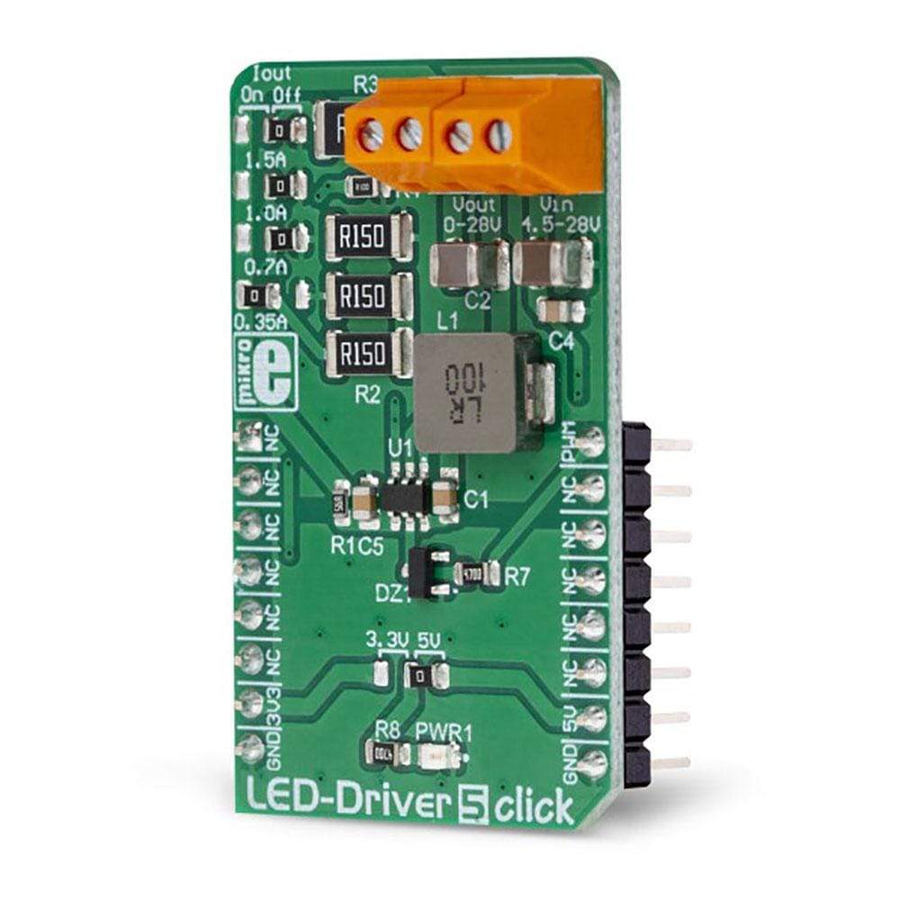
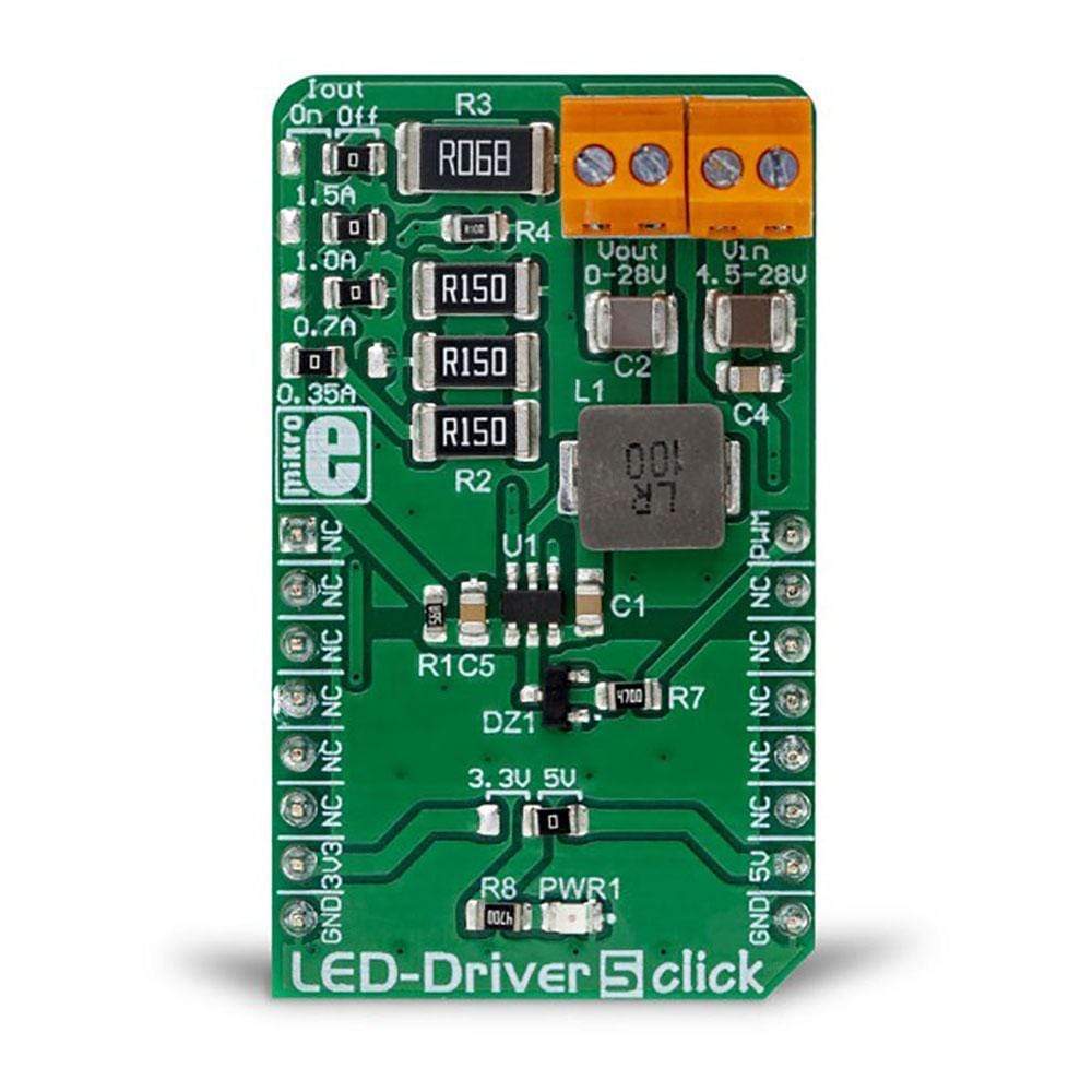
The LED Driver 5 Click Board™ is a Click Board™ capable of driving an array of high-power LEDs with constant current, up to 1.5A. This Click Board™ features the TPS54200, a highly integrated LED driver IC, with many useful features. It consists of a synchronous, fixed-frequency buck converter which operates at 600kHz, providing an excellent size/efficiency ratio.
The LED Driver 5 Click Board™ can use both analog and PWM control signal for dimming the connected LED array.
Downloads
The TPS54200 supports analog and PWM dimming mode. In analog dimming mode, the internal reference voltage is scaled in the range from 1% to 100%. In the PWM dimming mode, the LED output is synchronized with the PWM control signal at the input. The smart signal-switching logic automatically selects the dimming mode by examining the signal applied to the PWM pin. LED Driver 5 click is an ideal solution for driving a single or multi-stream LED arrays, including monochrome, white, and IR LED arrays, providing up to 28V at the output.
How Does The LED Driver 5 Click Board™Work?
The LED Driver 5 Click Board™ is based on the TPS54200, a synchronous buck converter designed to drive monochrome, color, and IR LED arrays made by Texas Instruments. The LED Driver 5 Click Board™ is very flexible regarding the input voltage choice, allowing any voltage in the range from 4.5V up to 28V to be used. This is possible thanks to the TPS54200 driver IC, which integrates a buck converter IC, and supports an LED dimming by using the pulse width of the PWM signal on the control input. This IC has a mode selection logic circuitry which is used to select one of two dimming modes, depending on the incoming PWM control signal level.
The PWM pin is used to control more than just one function. Besides choosing the dimming mode (analog or PWM), this pin is also used to enable or disable the IC. If the signal at the PWM pin rises above the threshold value (0.56V typically) the IC will be enabled. Keeping the voltage at the PWM pin lower than 0.56V for at least 40 ms will effectively disable the IC.
After the device is enabled, the magnitude of the PWM signal is detected and stored by an internal peak detector. The voltage of the peak detector is then compared with two threshold values, V ADIM and V PDIM , after 300 µs. If the peak detector output is at a higher voltage than 2.07V, analog dimming mode will be selected and locked. If the peak detector voltage is in the range between 1V and 2.07V, the PWM dimming mode will be selected and locked. If the voltage is less than 1V, the whole detection process will be repeated after 300 µs, until one of two operating modes is selected and locked. Once locked, the dimming mode can only be changed by cycling the VIN voltage or re-enabling the IC. The PWM pin is routed to the PWM pin of the mikroBUS™, allowing it to be controlled by the host microcontroller (MCU).
When the analog dimming mode is selected (the magnitude of the control PWM signal is above 2.06V during the boot-up sequence of the TPS54200), the internal reference voltage (V REF ) is scaled down according to the duty cycle of the PWM signal applied to the PWM pin. The internal reference voltage for this mode is 200 mV at full-scale (duty-cycle at 100%). As the duty cycle decreases, the reference voltage is scaled down to 1% of its value. This will cause the current through the LED to be scaled as well, effectively dimming the LED. This type of dimming, where the LED intensity is dimmed to a very low-level invisible to the eye, is sometimes referred to as deep-dimming. The PWM control signal at the PWM pin should stay within the range of 10 kHz, to reduce the output voltage ripple.
If the PWM dimming mode is selected (the magnitude of the control PWM signal is between 1V and 2.06V during the boot-up sequence of the TPS54200), the internal reference voltage is fixed at 100mA. In this mode, the LED dimming is performed by using the PWM signal applied to the PWM pin, modulating the LED output. Holding the internal reference voltage fixed, the LED at the output will only be switched ON or OFF, according to the duty cycle of the control PWM signal.
The buck converter itself is a very feature-rich circuitry, a synchronous buck converter, operating at the fixed frequency of 600kHz. This offers an excellent size/efficiency ratio, keeping the footprint of the TPS54200 IC very small. Features such as the open LED or shorted LED detection, overvoltage, and under-voltage protection, over-current and open loop protection, thermal shutdown, soft start function that prevents the inrush current, allow the LED Driver 5 Click Board™ to be a very reliable and safe solution for driving high current LEDs or LED arrays.
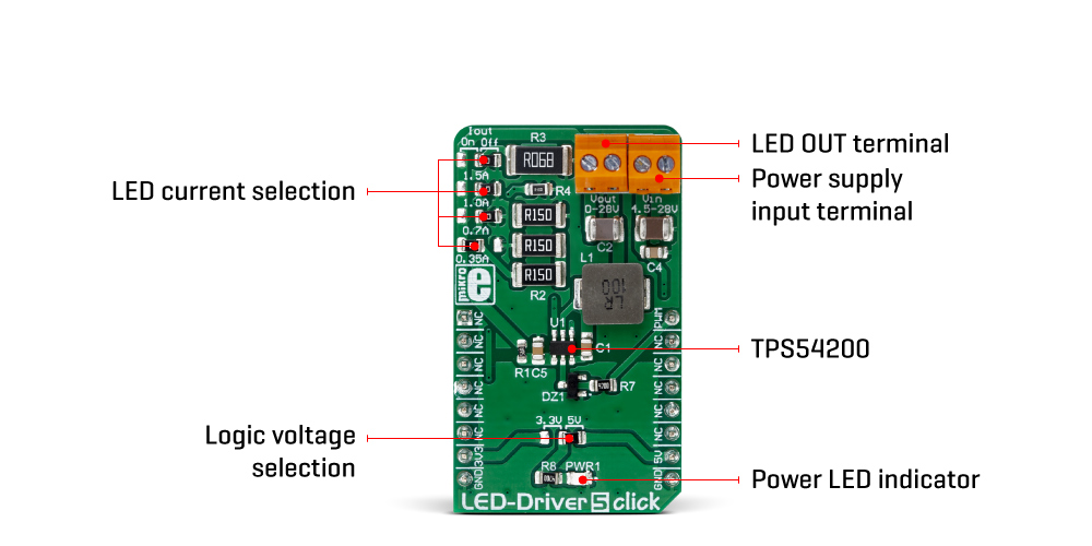
The LED Driver 5 Click Board™ contains four SMD jumpers used to select the current through the LED array. They are grouped together and labeled as I OUT . There are four different settings: 0.35A, 0.7A, 1A, and 1.5A. Switching the current selection SMD jumper to the ON position will connect a respective sensing resistor (R S )to the circuit. The value of each R S is calculated using a very simple formula, given in the datasheet of the TPS54200 IC:
Note that switching two SMD jumpers to the ON position simultaneously will cause them to form a parallel connection with its equivalent resistance. However, this is not recommended since almost all the resistor combinations will result with the value too low to be used (the LED current will be set to above 1.5A, thus triggering the protection circuit)
SPECIFICATIONS
| Type | LED Drivers |
| Applications | The LED Driver 5 Click Board™ is an ideal solution for a reliable and efficient driving of a single or multi-stream LED arrays, including monochrome LED, white LED, and IR LED arrays, providing up to 28V at the output |
| On-board modules | TPS54200, a synchronous buck converter for driving monochrome, color, and IR LED arrays |
| Key Features | Highly regulated, selectable LED current, can use a wide range of power supply voltages, open LED or shorted LED detection, overvoltage and undervoltage protection, over-current and open-loop protection, thermal shutdown, soft start function prevents the inrush current |
| Interface | PWM |
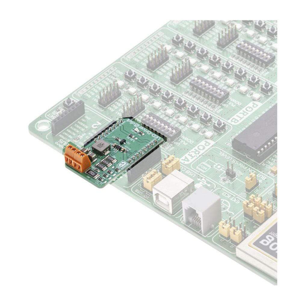
| Compatibility | mikroBUS |
| Click board size | M (42.9 x 25.4 mm) |
| Input Voltage | 3.3V or 5V |
PINOUT DIAGRAM
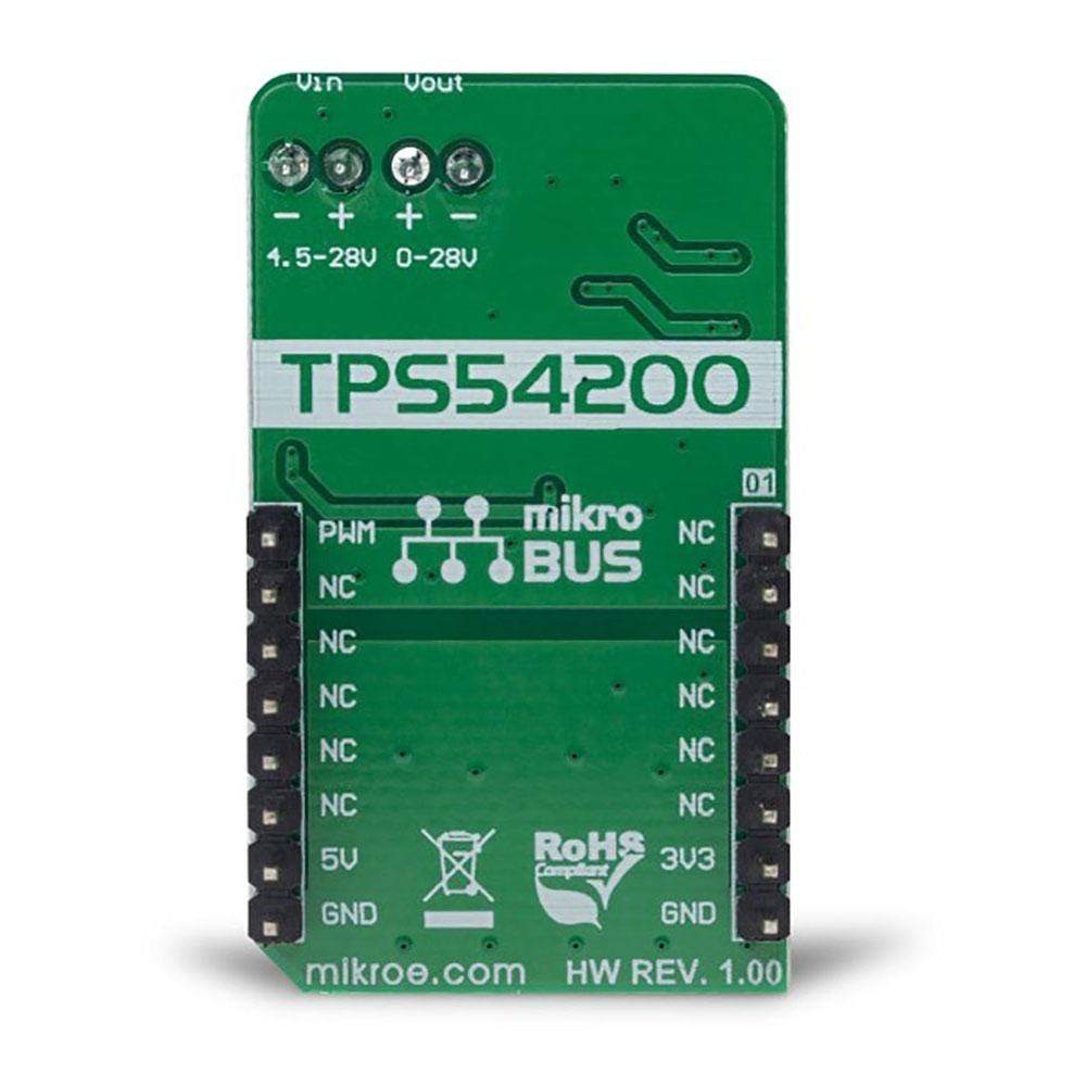
This table shows how the pinout on the LED Driver 5 Click Board™ corresponds to the pinout on the mikroBUS™ socket (the latter shown in the two middle columns).
| Notes | Pin | Pin | Notes | ||||
|---|---|---|---|---|---|---|---|
| NC | 1 | AN | PWM | 16 | PWM | Control PWM Signal | |
| NC | 2 | RST | INT | 15 | |||
| EN | 3 | CS | RX | 14 | |||
| NC | 4 | SCK | TX | 13 | |||
| NC | 5 | MISO | SCL | 12 | |||
| NC | 6 | MOSI | SDA | 11 | |||
| Power supply | 3.3V | 7 | 3.3V | 5V | 10 | 5V | Power supply |
| Ground | GND | 8 | GND | GND | 9 | GND | Ground |
ONBOARD SETTINGS AND INDICATORS
| Label | Name | Default | Description |
|---|---|---|---|
| PWR1 | PWR | - | Power LED indicator |
| TB2 | Vin | - | Power supply input terminal |
| TB1 | Vout | - | LED output terminal |
| JP1-JP3 | 1.5A, 1A, 0.7A | OFF | LED current selection: left position ON, right position OFF |
| JP4 | 0.35A | ON | LED current selection: left position ON, right position OFF |
| General Information | |
|---|---|
Part Number (SKU) |
MIKROE-3297
|
Manufacturer |
|
| Physical and Mechanical | |
Weight |
0.02 kg
|
| Other | |
EAN |
8606018714124
|
Frequently Asked Questions
Have a Question?
Be the first to ask a question about this.