


Mikroelektronika d.o.o.
Accel 10 Click Board™
Accel 10 Click Board™
SKU: MIKROE-4112
Couldn't load pickup availability


Overview
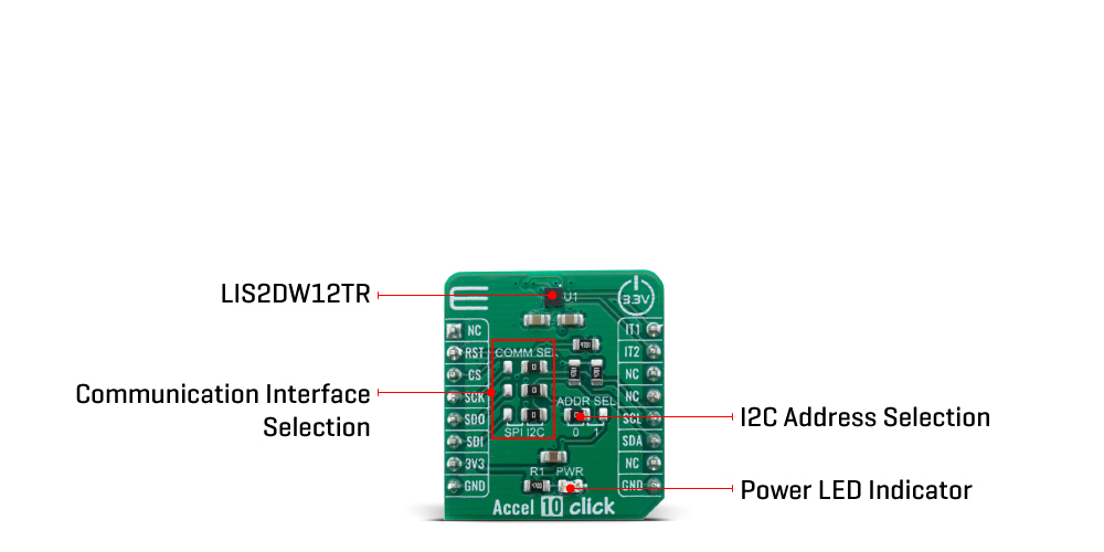
The Accel 10 Click Board™ features an ultra-low power triaxial "Femto" accelerometer sensor with embedded intelligence, labelled as the LIS2DW12TR. This Click Board™ allows linear motion and gravitational force measurements in ranges of ±2 g, ±4 g, ±8, and ±16 g in three perpendicular axes. This smart sensor allows the Accel 10 Click to detect many different events, including tap, double-tap, free-fall detection, and more, making it well suited for using it in handheld or wearable devices. It features onboard data processing, offering the acceleration data directly, over the standard I2C or SPI interface.
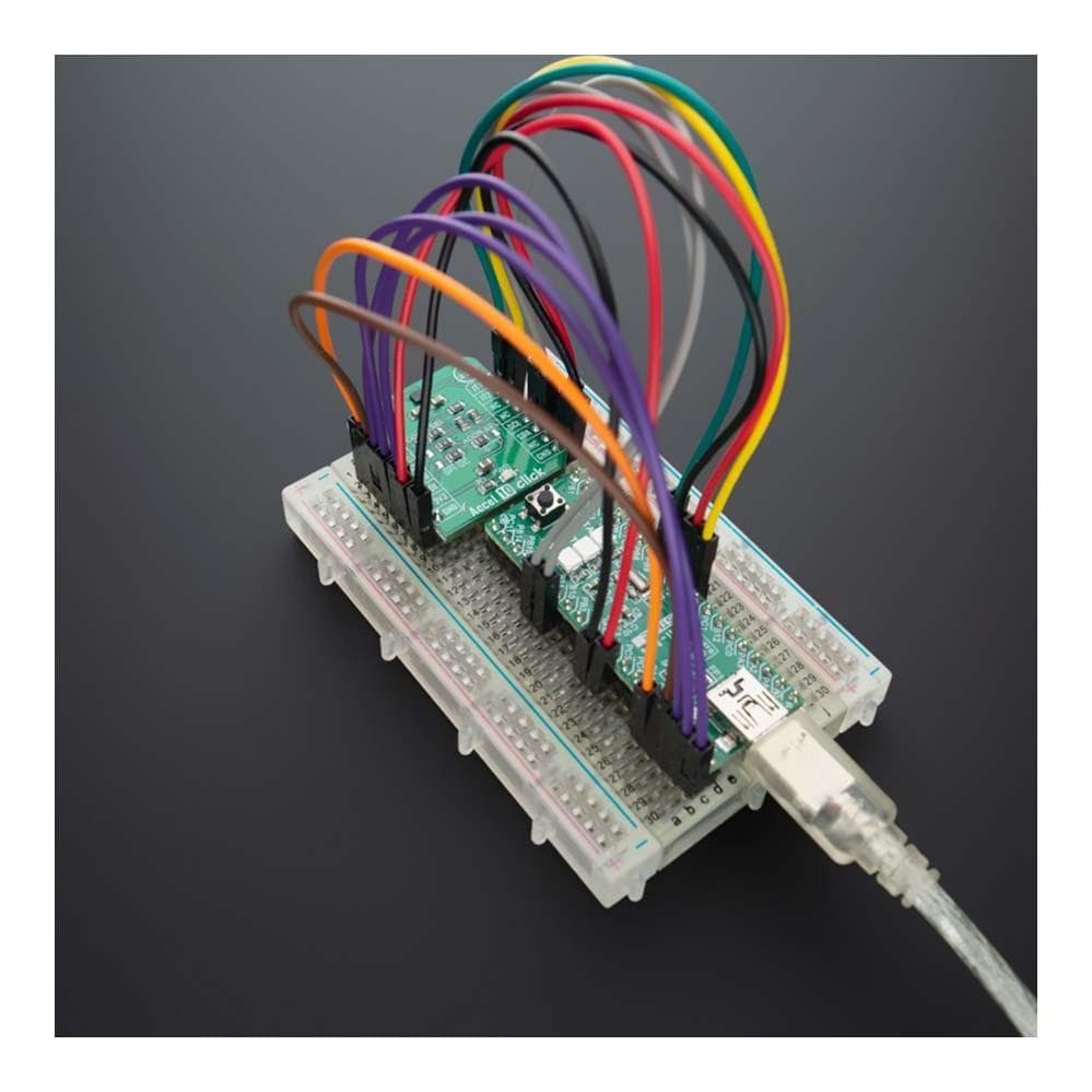
The Accel 10 Click Board™ is supported by a mikroSDK compliant library, which includes functions that simplify software development. This Click Board™ comes as a fully tested product, ready to be used on a system equipped with the mikroBUS™ socket.
The sensor can use any of its two interrupt pins to report a detected event.
Downloads
How Does The Accel 10 Click Board™ Work?
The Accel 10 Click Board™ is based on the LIS2DW12TR, a high-performance ultra-low-power 3-axis "femto" accelerometer, from STMicroelectronics. This sensor has many features perfectly suited for wearables, handheld, and IoT applications, offering a good balance between the performance and the power consumption. One of its key features is its extremely low power consumption, which makes it perfectly suited for such applications. There are several power modes which the LIS2DW12TR device can use. While in Low Power mode, the device consumes only 0.38µA, but the access to some features is restricted. Having that in mind, accel 10 Click can be used for a rapid development and testing of various applications based on step counting, fitness applications, profile switching and display ON/OFF applications, angle measurement applications, and similar applications. More information can be found within the LIS2DW12TR datasheet.
The LIS2DW12TR sensor can measure acceleration within ranges of ±2 g, ±4 g, ±8, and ±16 g. It can output the measurement data using the Output Data Rate (ODR) from 1.6Hz (Low Power mode), up to 1600Hz (Performance mode). A high-precision analog front end facilitates highly sensitive MEMS, featuring a 14-bit A/D Converter. It allows very high accuracy of the output, even during very low amplitude changes. This makes the sensor particularly sensitive and accurate with movements that generate relatively low acceleration signals. However, using a highly sensitive MEMS makes the LIS2DW12TR prone to damage caused by extremely high g-forces (10,000 g for less than 200 µs).
Acceleration data is available in 14-bit format from both the data registers and the internal FIFO buffer, which can can memorize 32 slots of X, Y and Z data. The FIFO buffer can be used for more complex calculations or timed readings, reducing the traffic on the communication interface. FIFO buffer allows optimization within the firmware that runs on the host MCU.
Besides the acceleration MEMS and complementary analog front-end circuit, the LIS2DW12TR sensor also has an integrated temperature sensor. It is updated up to 25 times per second, and sampled to an 12-bit value (complement of 2's format).
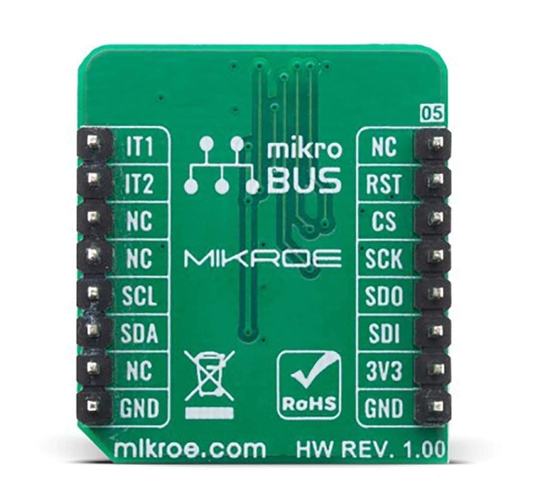
Interrupts can be triggered for many different events. Some basic events include the data-ready interrupt event and aforementioned FIFO events, while so-called feature engines can trigger an interrupt for any of the detected motion/movement events, including step detection/counter, activity recognition, tilt on wrist, tap/double tap, any/no motion, and error event interrupt. The extensive interrupt engine can use two programmable interrupt pins. Both of these pins can be assigned with any interrupt source and can be either LOW or HIGH on interrupt, depending on settings in appropriate registers. These two pins are routed to PWM and INT pin of the mikroBUS™, and are labeled as IT1 and IT2, respectively.
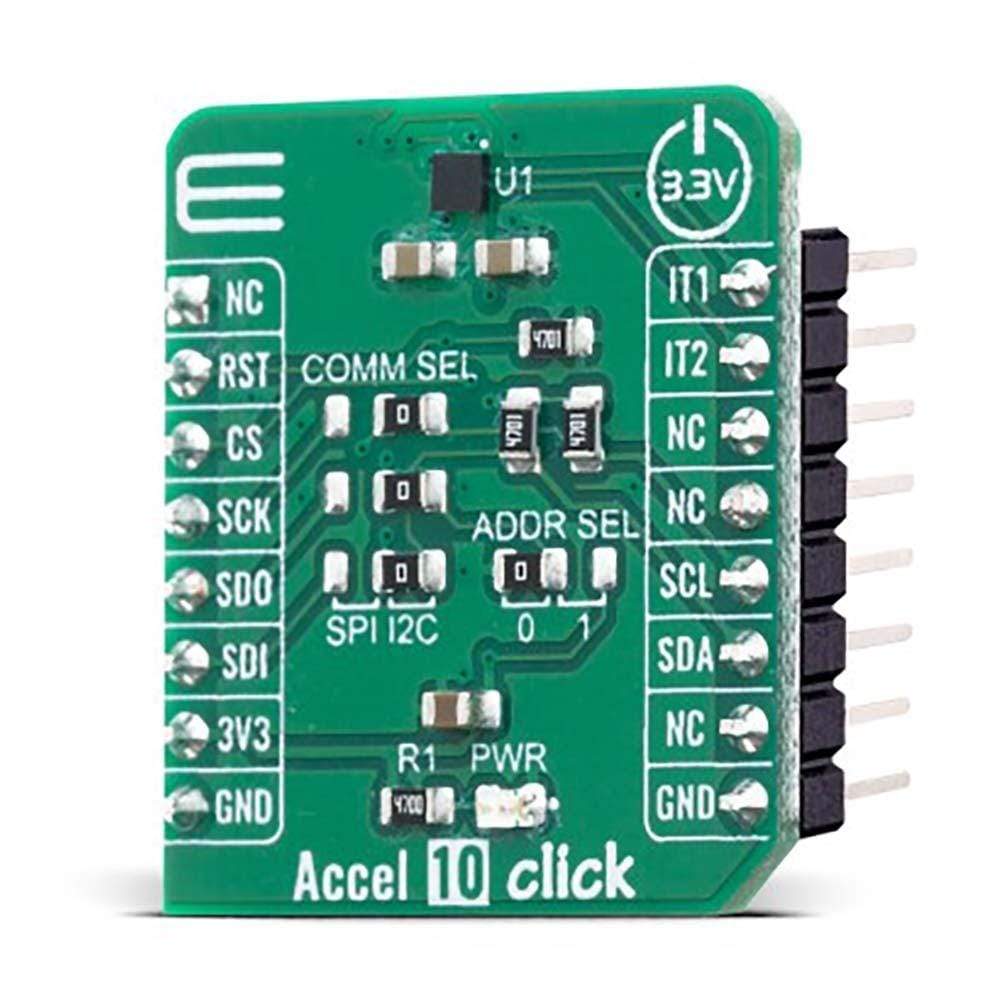
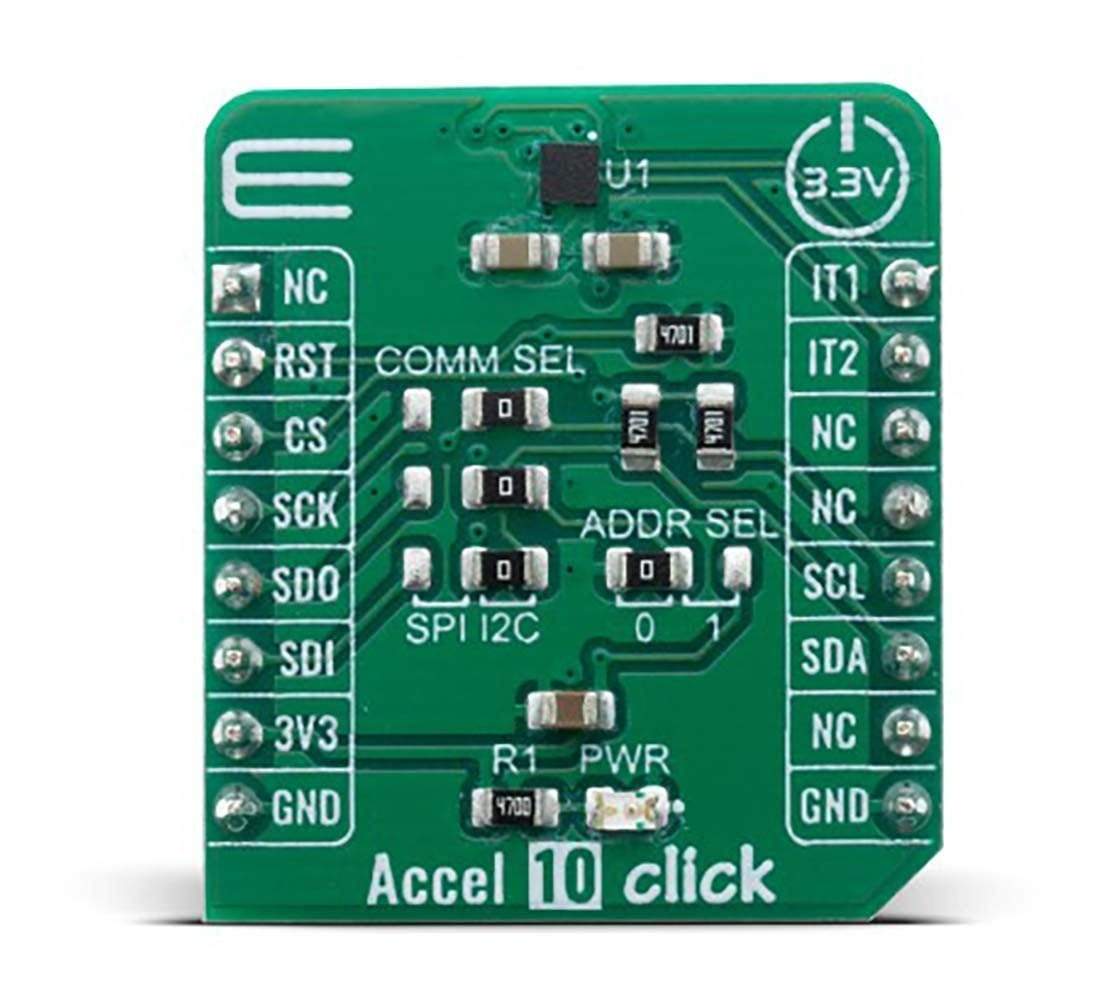
The Accel 10 Click Board™ offers two communication interfaces. It can be used with either I2C or SPI. The onboard SMD jumpers labeled as COMM SEL allow switching between the two interfaces. Note that all the jumpers have to be positioned either I2C or to SPI position. When I2C interface is selected, an additional SMD jumper labeled as ADDR SEL becomes available, determining the least significant bit of the LIS2DW12TR I2C address.
The Accel 10 Click Board™ uses both I2C and SPI communication interfaces. It is designed to be operated only with 3.3V logic levels. A proper logic voltage level conversion should be performed before the Click board™ is used with MCUs with logic levels of 5V.
SPECIFICATIONS
| Type | Acceleration,Motion |
| Applications | The Accel 10 Click Board™ can be used for a rapid development and testing of various applications based on step counting, fitness applications, profile switching and display ON/OFF applications, angle measurement applications, and similar applications. |
| On-board modules | LIS2DW12TR, a 14-bit triaxial acceleration sensor with ultra-low power consumption, from STMicroelectronics. |
| Key Features | tap, double tap and free-fall detection, ultra-low power consumption, thermal readings |
| Interface | GPIO,I2C,SPI |
| Compatibility | mikroBUS |
| Click board size | S (28.6 x 25.4 mm) |
| Input Voltage | 3.3V |
PINOUT DIAGRAM
This table shows how the pinout on the Accel 10 Click Board™ corresponds to the pinout on the mikroBUS™ socket (the latter shown in the two middle columns).
| Notes | Pin | Pin | Notes | ||||
|---|---|---|---|---|---|---|---|
| NC | 1 | AN | PWM | 16 | I1 | INT OUT 1 | |
| NC | 2 | RST | INT | 15 | I2 | INT OUT 2 | |
| SPI Chip Select | CS | 3 | CS | RX | 14 | NC | |
| SPI Clock | SCK | 4 | SCK | TX | 13 | NC | |
| SPI Data OUT | SDO | 5 | MISO | SCL | 12 | SCL | I2C Clock |
| SPI Data IN | SDI | 6 | MOSI | SDA | 11 | SDA | I2C Data |
| Power Supply | 3.3V | 7 | 3.3V | 5V | 10 | NC | |
| Ground | GND | 8 | GND | GND | 9 | GND | Ground |
ONBOARD SETTINGS AND INDICATORS
| Label | Name | Default | Description |
|---|---|---|---|
| LD1 | PWR | - | Power LED Indicator |
| JP1,JP2,JP4 | COM SEL | Right | Communication interface selection: right position SPI, left position I2C |
| JP3 | ADD SEL | Left | I2C address LSB selection: left position 0, right position 1 |
ACCEL 10 CLICK ELECTRICAL SPECIFICATIONS
| Description | Min | Typ | Max | Unit |
|---|---|---|---|---|
| Receiver inputs voltage range | ±2 | - | ±16 | g |
| Receiver inputs voltage range | 1.6 | - | 1600 | Hz |
| Receiver inputs voltage range | -40 | - | +85 | °C |
| Receiver inputs voltage range | - | 90 | - | µA |
| Receiver inputs voltage range | 0.38 | - | 5 | µA |
| General Information | |
|---|---|
Part Number (SKU) |
MIKROE-4112
|
Manufacturer |
|
| Physical and Mechanical | |
Weight |
0.015 kg
|
| Other | |
EAN |
8606018717422
|
Frequently Asked Questions
Have a Question?
Be the first to ask a question about this.