
Tag-Connect, LLC
Tag Connect TC2050-IDC-050-ALL-20 Programming Cable
Tag Connect TC2050-IDC-050-ALL-20 Programming Cable
SKU: TC2050-IDC-050-ALL-20
Couldn't load pickup availability


Key Features
Overview
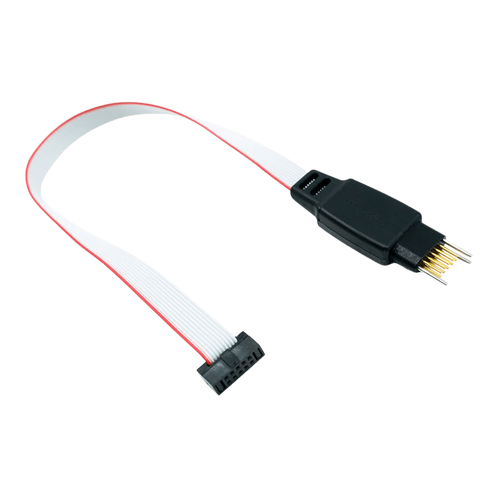
The Tag Connect TC2050-IDC-050-ALL-20 represents a space-saving solution for ARM Cortex development, eliminating traditional programming headers whilst maintaining full debugging capability. This legged variant provides secure connection during extended debugging sessions through integrated retention clips.
Compatible with ARM Keil ULINK2, IAR I-JET, and other debuggers featuring Samtec FTSH-110-01 style connectors. The cable maintains 1:1 pin mapping for the first ten connections, optimising signal integrity for JTAG and SWD protocols.
Engineers choose this solution when PCB space is premium but robust debugging access remains essential. The spring-pin technology delivers over 100,000 connection cycles, making it suitable for both development and production programming scenarios.
Related products: TC2050-IDC-NL-050-ALL-20 No Legs variant and TC2050-ARM2010 adapter for standard 20-pin JTAG interfaces.
Downloads
Why Engineers Choose The Tag Connect TC2050-IDC-050-ALL-20 Programming Cable
Space-Critical Designs
Production Programming
Development Efficiency
Professional Programming Cable for ARM Cortex Debugging
The Tag Connect TC2050-IDC-050-ALL-20 cable eliminates the need for expensive programming headers on your PCB whilst providing reliable JTAG and SWD debugging capabilities. This professional-grade cable connects directly to a minimal footprint on your target board, saving both cost and space on every PCB.
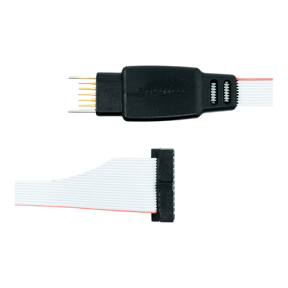
Direct PCB Connection - No Header Required
The spring-loaded pogo pins make secure contact with your PCB pads through precise alignment holes. The "with legs" design features retaining clips that lock the cable in place during debugging sessions, eliminating the need to hold the cable manually whilst setting breakpoints or stepping through code.
ULINK2 & ARM Cortex Compatibility
Designed specifically for ARM Keil ULINK2 debuggers and similar tools using the Samtec FTSH-110-01 style 20-pin 0.050" pitch micro-header. The cable connects pins 1-10 from the TC2050 footprint to pins 1-10 of the 20-pin connector, with pins 11-20 left unconnected as per standard ARM debugging protocols.
| Pin | Signal | Description |
|---|---|---|
| 1 | VCC | Target reference voltage |
| 2 | SWDIO/TMS | Serial Wire Debug I/O / JTAG Test Mode Select |
| 3 | GND | Ground |
| 4 | SWCLK/TCK | Serial Wire Clock / JTAG Test Clock |
| 5 | GND | Ground |
| 6 | SWO/TDO | Serial Wire Output / JTAG Test Data Out |
| 7 | KEY | Keying (no pin) |
| 8 | TDI/NC | JTAG Test Data In / Not Connected |
| 9 | GND | Ground |
| 10 | nRESET | Target reset (active low) |
Wiring Quick-Start
PCB footprint requirements:
Pad diameter: 0.0197" (0.5mm) Hole diameter: 0.0138" (0.35mm) for alignment pins Pad spacing: 0.050" (1.27mm) between rows Footprint area: 0.35" x 0.125" (8.9mm x 3.2mm) Connect the 20-pin IDC connector to your ULINK2 debugger with pin 1 aligned to the red stripe on the ribbon cable. The TC2050 end aligns with your PCB footprint using the three precision guide holes.
| General Information | |
|---|---|
Part Number (SKU) |
TC2050-IDC-050-ALL-20
|
Manufacturer |
|
| Physical and Mechanical | |
Weight |
0.1 kg
|
| Other | |
EAN |
5055383665464
|
Frequently Asked Questions
Have a Question?
-
How does this compare to traditional 20-pin JTAG headers?
This solution eliminates the connector cost and 0.9" x 0.6" board space required by traditional headers whilst providing identical debugging functionality.
-
What signals are available on the TC2050 footprint?
The footprint provides VCC reference, SWDIO/TMS, SWCLK/TCK, SWO/TDO, TDI, nRESET, and multiple ground connections for comprehensive debugging.
-
Can I use this with 3.3V target systems?
Yes, the cable supports target voltages from 1.65V to 5.5V. Pin 1 provides voltage reference to the debugger, not power supply.
-
Is this cable suitable for production programming?
Yes, the spring pins are rated for over 100,000 operations, making it suitable for high-volume production programming scenarios.
-
How do I create the PCB footprint for this cable?
Download the official TC2050-IDC datasheet from Tag-Connect for precise pad dimensions, hole sizes, and spacing requirements for your PCB design.
-
What's the difference between legged and no-legs versions?
The legged version (this cable) has retention clips for secure hands-free connection. The no-legs version requires manual holding or the TC2050-CLIP accessory.
-
Can I use this cable with STM32 microcontrollers?
Yes, this cable supports ARM Cortex-M debugging including STM32 devices. Ensure your debugger supports the 0.050" pitch connector interface.
-
What PCB thickness range is supported?
The standard cable supports PCB thicknesses from 0.032" to 0.093" (0.8mm to 2.4mm). For thicker boards, use the TC2050-IDC-LONGLEGS variant.
-
How does this differ from the standard TC2050-IDC-050 cable?
The TC2050-IDC-050-ALL-20 connects all 10 pins including TDI (pin 8), whereas the standard version leaves pins 5 and 9 unconnected. This provides full JTAG functionality.
-
What debuggers are compatible with the TC2050-IDC-050-ALL-20 cable?
This cable works with ARM Keil ULINK2, IAR I-JET, ARM ULINK Pro, and any debugger using Samtec FTSH-110-01 style 20-pin 0.050" pitch connectors.