


Mikroelektronika d.o.o.
MP3 2 Click Board™
MP3 2 Click Board™
SKU: MIKROE-4159
Couldn't load pickup availability
Overview
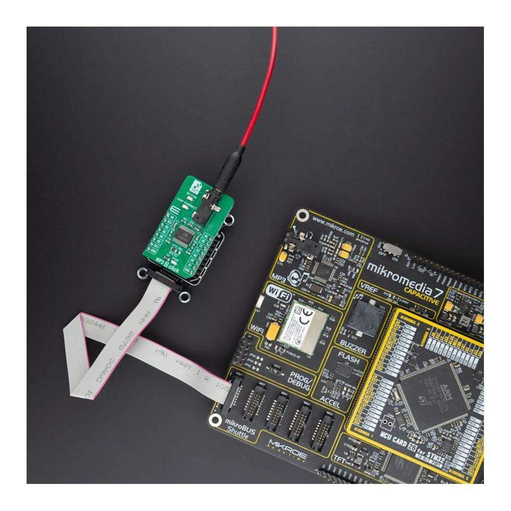
The MP3 2 Click Board™ is an audio decoder expansion board with an onboard microSD card slot, that enables you to create your personal audio playback system. It holds the KT403A, a SOC chip solution with intergraded MCU, hardware audio MP3/WAV decoder and DSP, from Shenzhen Qianle Microelectronics Technology Co. Ltd.
All the mentioned integrated hardware components enable the MP3 2 Click Board™ board to guarantee good stability and tone quality. You are able to use UART serial communication to control this board and do diverse operations with music files from microSD cards such as Play, Pause, Volume Up/Down, and many more. These features make MP3 2 Click Board™ the ideal solution for audio devices, in any application that demands an Audio Playback Module for MP3, WAV.
Downloads
How Does The MP3 2 Click Board™ Work?
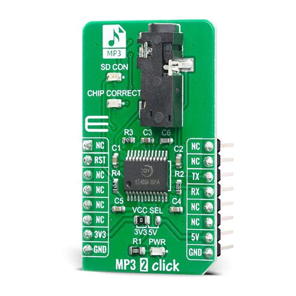
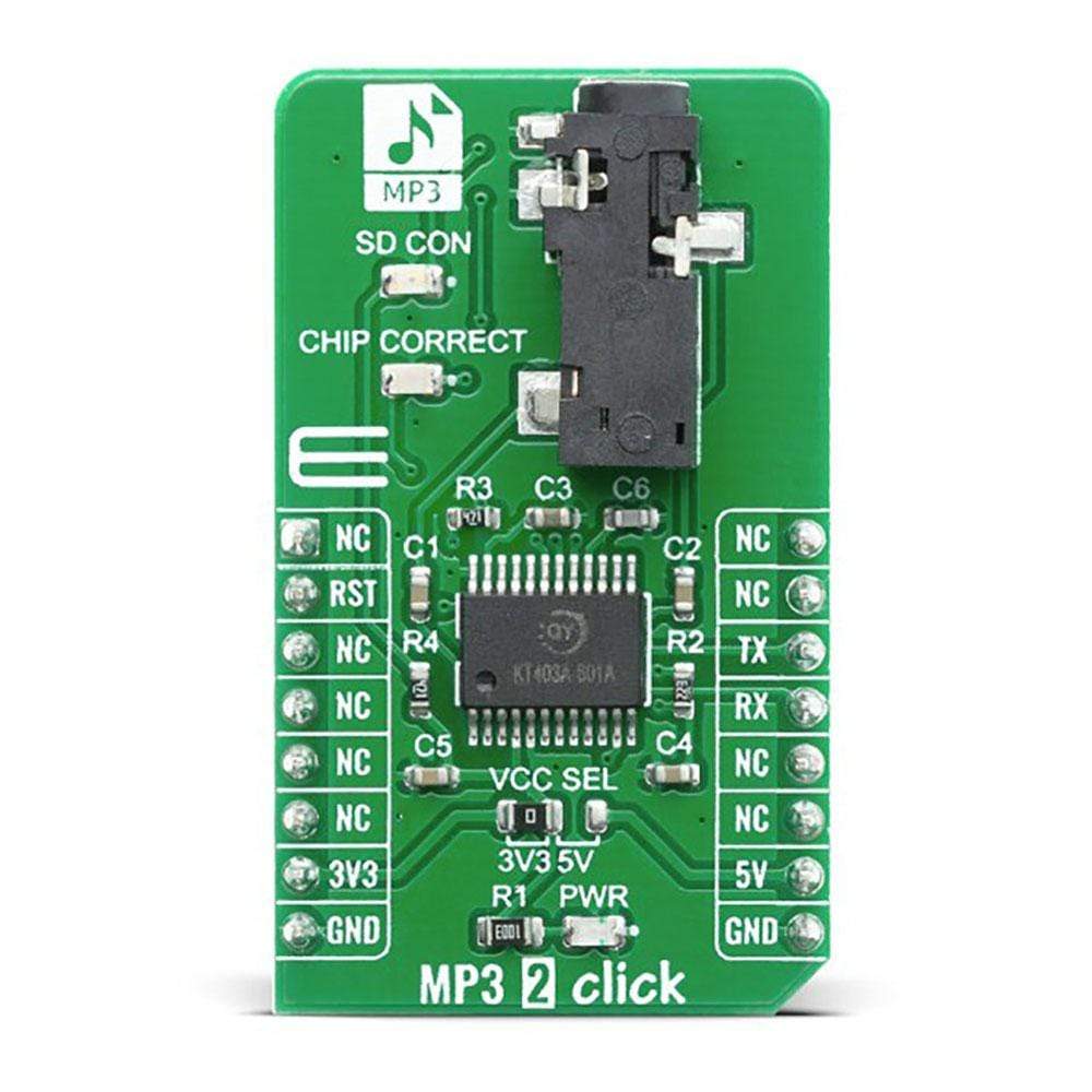
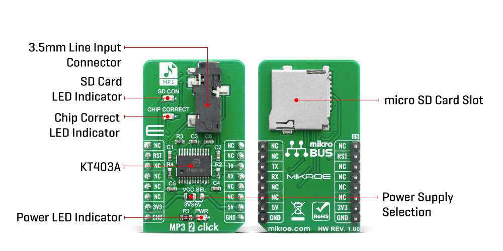
The MP3 2 Click Board™ is equipped with the KT403A as a main integrated circuit, micro SD card connector, and 3.5mm Audio Jack connector. Basically, it is a complete solution for a DAP (digital audio player) on a Click board, which can be controlled over the UART communication interface, using RX and TX pins of the mikroBUS™ socket. The default baud rate is 9600bps and it is customizable.
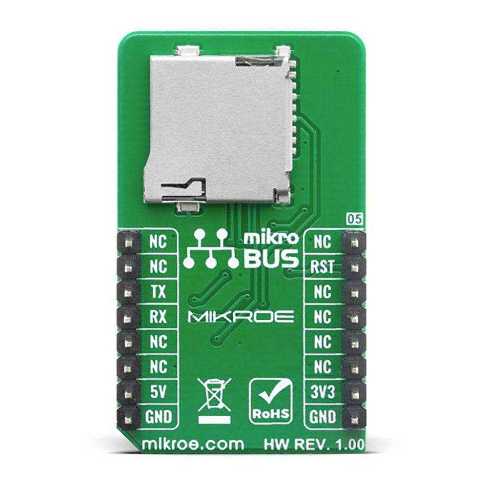
On the MP3 2 Click Board™, the KT403A serves as a brain. It is complete SOC, which integrates16-bit MCU, audio decoder, and a 24-bit DSP. It also integrates the complete SD card interface and therefore, this click board contains the connector onboard for an external micro SD card. Thanks to that, the user can insert a fair amount of memory if the long, continuous playback time is needed.
The MP3 2 Click Board™ has two status indication LEDs, onboard. The first one is named "SD Card" and it serves as an indication that the SD Card is present in the slot. The other one is "Chip Correct" and it indicates that the SD Card is correct and that the communication between the KT403A and the SD Card sucseeded. Besides the indicatora, there is one 3.5mm headphone jack onboard, so that MP3 2 Click can be connected directly to the next stage of the music playback system, ie. audio amplifier.
Using the predefined command set, the MP3 2 Click Board™ can be fully controlled. One can Play/Pause a song, play a specific track, change a Volume Up and Volume Down between 0% and 100%, play the next or the previous song, repeat the current song, and more. Besides that, several sound effects are also supported, mentioned for different types of music: Normal, Jazz, Classic, Pop, and Rock.
The MP3 2 Click Board™ can be supplied and interfaced with both 3.3V and 5V without the need for any external components. The onboard SMD jumper labeled as VCC SEL allows voltage selection for supply IC, but this Click Board™ communication interface and is designed to be operated only with a 3.3V logic level.
SPECIFICATIONS
| Type | MP3 |
| Applications | Digital music players, camcorders, speakers, headphones, toys, and more. |
| On-board modules | KT403A serial MP3 module, from Shenzhen Qianle Microelectronics Technology Co. Ltd. |
| Key Features | MP3 Player, Streaming support for MP3 and WAV. |
| Interface | UART |
| Compatibility | mikroBUS |
| Click board size | M (42.9 x 25.4 mm) |
| Input Voltage | 3.3V or 5V |
PINOUT DIAGRAM
This table shows how the pinout on the MP3 2 Click Board™ corresponds to the pinout on the mikroBUS™ socket (the latter shown in the two middle columns).
| Notes | Pin | Pin | Notes | ||||
|---|---|---|---|---|---|---|---|
| NC | 1 | AN | PWM | 16 | NC | ||
| Reset | RST | 2 | RST | INT | 15 | NC | |
| NC | 3 | CS | RX | 14 | TX | UART TX | |
| NC | 4 | SCK | TX | 13 | RX | UART RX | |
| NC | 5 | MISO | SCL | 12 | NC | ||
| NC | 6 | MOSI | SDA | 11 | NC | ||
| Power Supply | 3.3V | 7 | 3.3V | 5V | 10 | 5V | Power |
| Ground | GND | 8 | GND | GND | 9 | GND | Ground |
ONBOARD SETTINGS AND INDICATORS
| Label | Name | Default | Description |
|---|---|---|---|
| LD1 | PWR | - | Power LED Indicator |
| JP1 | VCC SEL | Left | Power Supply Voltage Selection: Left position 3V3, right position 5V |
| LD2 | CHIP CORRECT | - | Chip correct LED indicator |
| LD3 | SD CON | - | SD Card connect LED indicator |
| General Information | |
|---|---|
Part Number (SKU) |
MIKROE-4159
|
Manufacturer |
|
| Physical and Mechanical | |
Weight |
0.019 kg
|
| Other | |
EAN |
8606018717712
|
Frequently Asked Questions
Have a Question?
Be the first to ask a question about this.