


Mikroelektronika d.o.o.
4-20mA T 2 Click Board™
4-20mA T 2 Click Board™
SKU: MIKROE-5540
Couldn't load pickup availability


Key Features
Overview
The 4-20mA T 2 Click Board™: Transmitting Analogue Output Current Made Easy!
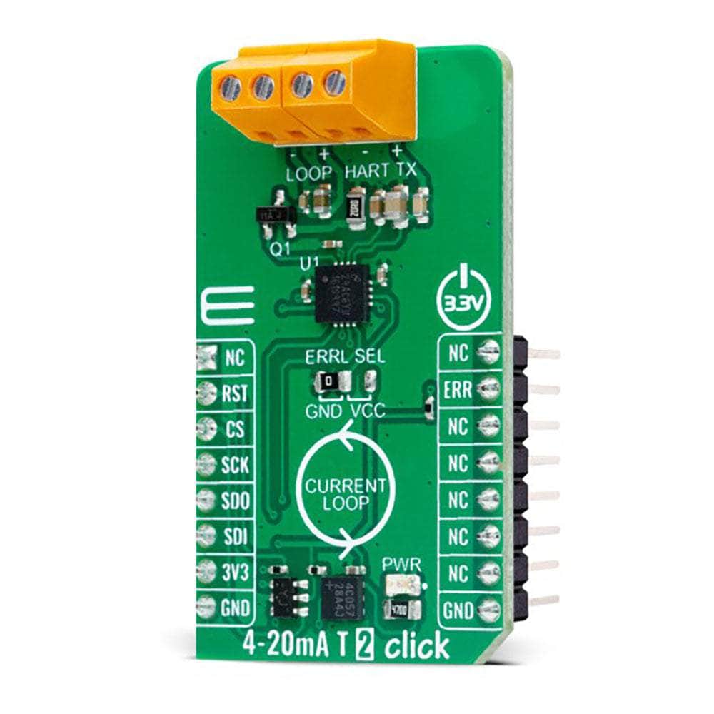
The 4-20mA T 2 Click Board™ is the ultimate solution for transmitting an analogue output current over an industry-standard 4-20mA current loop. This compact add-on board is designed to streamline your connectivity needs, providing seamless integration and reliable performance.
Powerful Features for Optimal Performance
At the heart of this remarkable Click Board™ is the DAC161S997, a low-power 16-bit ΣΔ digital-to-analogue converter (DAC) manufactured by the industry-leading Texas Instruments. With its advanced features, you can expect nothing short of exceptional performance.
One standout feature is the programmable Power-Up condition, allowing you to customize the behaviour of the Click Board™ upon power restoration. Additionally, the loop-error detection and reporting feature provides valuable insights into the performance of your current loop, ensuring smooth operation at all times.
The 4-20mA T 2 Click Board™ simplifies data transfer, and configuration of the DAC functions through a simple 4-wire SPI interface. This means you can effortlessly fine-tune the settings to suit your requirements, saving you valuable time and effort.
Efficiency and Flexibility Combined
Low power consumption is a key characteristic of the 4-20mA T 2 Click Board™. This ensures energy-efficient operation, prolonging the lifespan of your system and reducing overall power costs. Plus, with its compatibility with the Highway Addressable Remote Transducer (HART) modulator interface, you can seamlessly inject FSK-modulated digital data into the 4-20mA current loop, unlocking a world of possibilities.
Versatile Applications
The 4-20mA T 2 Click Board™ is the perfect choice for various applications. Whether you're working with 2-wire 4-20mA current loop transmitters, industrial process control systems, or low-power transmitters, this Click Board™ has got you covered.
Easy Software Development and Integration
With its mikroSDK-compliant library, the 4-20mA T 2 Click Board™ simplifies software development, allowing you to focus on what matters most - bringing your ideas to life. The library includes a range of functions that streamline the development process, ensuring a smooth and efficient experience.
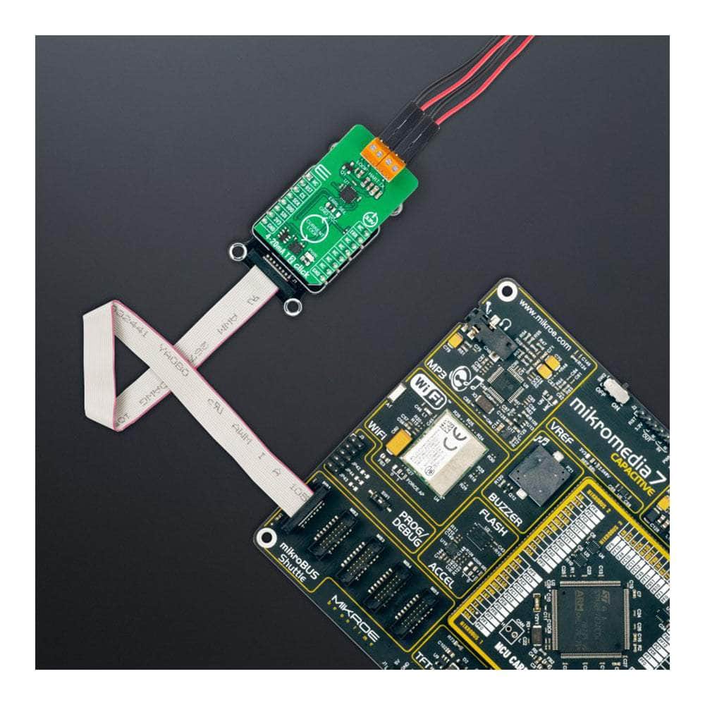
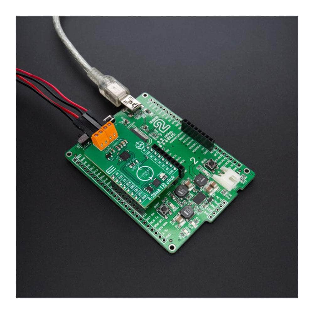
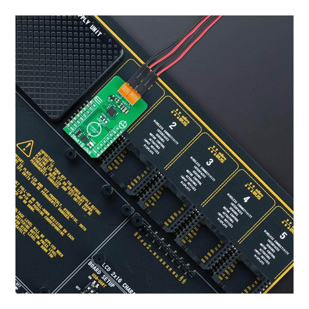
When you choose the 4-20mA T 2 Click Board™, you choose a fully tested product ready to be seamlessly integrated into your system. Equipped with the reliable mikroBUS™ socket, this Click Board™ guarantees effortless installation and compatibility.
Don't settle for anything less than excellence. Experience the power and convenience of the 4-20mA T 2 Click Board™ today!
Downloads
How Does The 4-20mA T 2 Click Board™ Work?
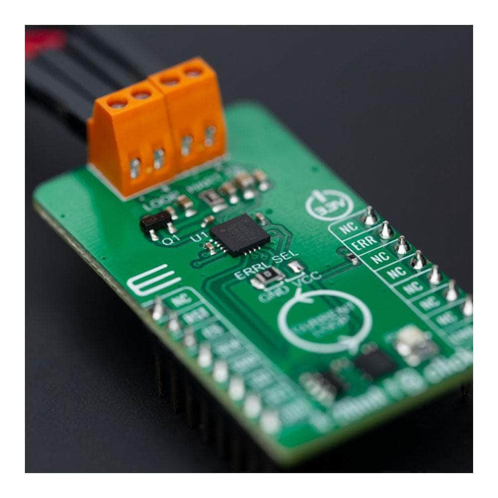
The 4-20mA T 2 Click Board™ is based on the DAC161S997, a low-power 16-bit ΣΔ digital-to-analog converter (DAC) from Texas Instruments, realized as a ΣΔ modulator. Next to ΣΔ DAC, the DAC161S997 also contains an internal ultra-low power voltage reference and an internal oscillator to reduce power and component count in compact loop-powered applications. This architecture, where DAC's output current represents a multiplied copy of the filtered modulator output, ensures an excellent linearity performance while minimizing the device's power consumption. In addition to an industry-standard 4-20 mA current loop over the LOOP terminal, the DAC161S997 also has the possibility of a simple Highway Addressable Remote Transducer (HART) modulator interfacing through an onboard HART TX terminal. It allows the injection of FSK-modulated digital data into the 4-20mA current loop.
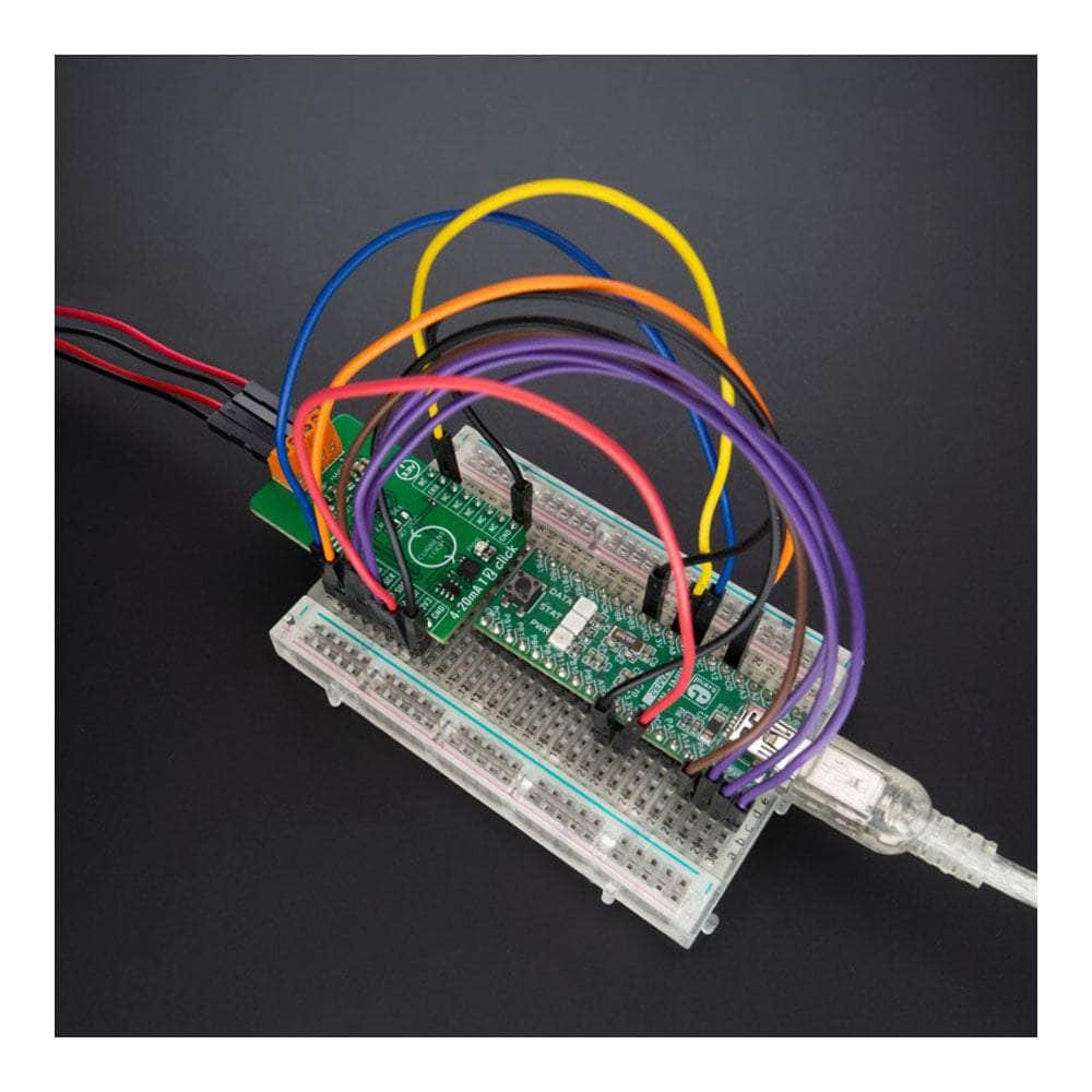
The 4-20mA T 2 Click Board™ communicates with MCU using a 4-wire SPI serial interface with a maximum frequency of 10MHz, for data transfer and configuration of the DAC functions. The DAC161S997 supports both Mode 0 and Mode 3 of the SPI protocol. 4-20mA T 2 Click comes with an additional feature, as an interrupt, available on the ERR pin of the mikroBUS™ socket, the loop-error detection/reporting feature. By default, the DAC161S997 detects and reports several types of errors: loop error, SPI timeout error (channel error), frame error, and alarm current.
In the case of a fault condition or during the initial Power-Up sequence, the DAC161S997 will output current in either the upper or lower error current band. The band's choice is user-selectable via the appropriate position of an onboard jumper ERRL SEL, while the current error value is programmable through the SPI interface.
The 4-20mA T 2 Click Board™ can only operate with a 3.3V logic voltage level. The board must perform appropriate logic voltage level conversion before using MCUs with different logic levels. However, the Click board™ comes equipped with a library containing functions and an example code that can be used as a reference for further development.
SPECIFICATIONS
| Type | Current |
| Applications | It can be used for 2-wire 4-20mA current loop transmitters, industrial process control, low-power transmitters, and more |
| On-board modules | DAC161S997 - 16-bit DAC for 4-20mA loops from Texas Instruments |
| Key Features | High resolution, industry-standard current loop, SPI-programmable, low power consumption, Power-Up programmable output current, loop-error detection and reporting, HART modulator interfacing, and more |
| Interface | SPI |
| Compatibility | mikroBUS |
| Click board size | M (42.9 x 25.4 mm) |
| Input Voltage | 3.3V |
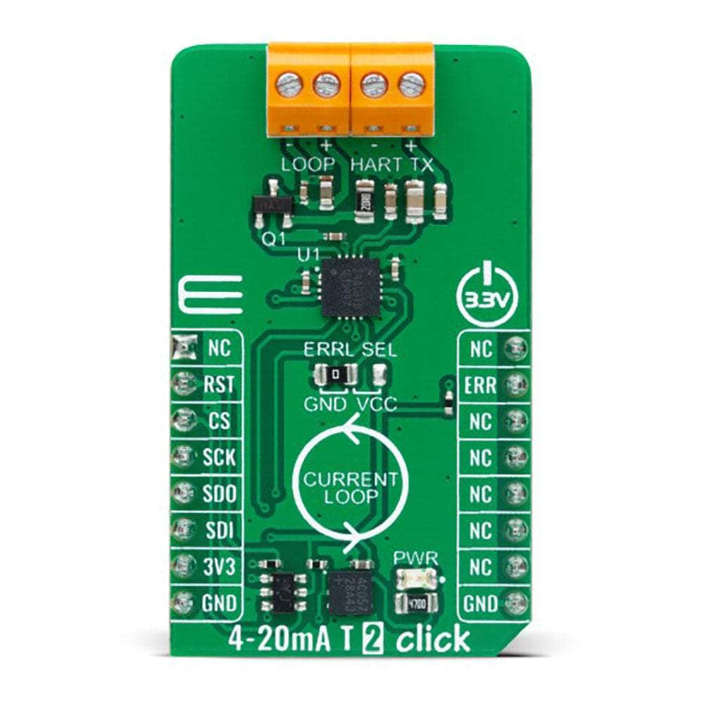
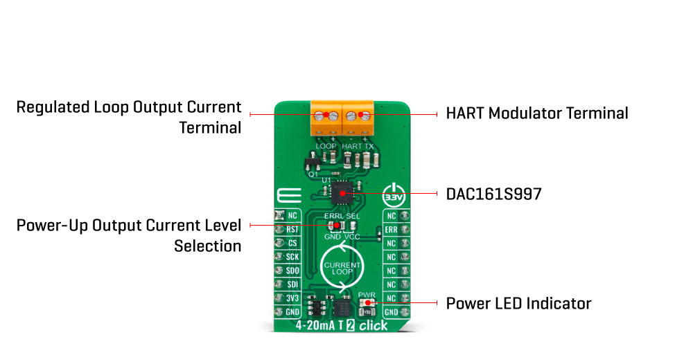
PINOUT DIAGRAM
This table shows how the pinout of the 4-20mA T 2 Click Board™ corresponds to the pinout on the mikroBUS™ socket (the latter shown in the two middle columns).
| Notes | Pin | Pin | Notes | ||||
|---|---|---|---|---|---|---|---|
| NC | 1 | AN | PWM | 16 | NC | ||
| NC | 2 | RST | INT | 15 | ERR | Loop-Error Interrupt | |
| SPI Chip Select | CS | 3 | CS | RX | 14 | NC | |
| SPI Clock | SCK | 4 | SCK | TX | 13 | NC | |
| SPI Data OUT | SDO | 5 | MISO | SCL | 12 | NC | |
| SPI Data IN | SDI | 6 | MOSI | SDA | 11 | NC | |
| Power Supply | 3.3V | 7 | 3.3V | 5V | 10 | NC | |
| Ground | GND | 8 | GND | GND | 9 | GND | Ground |
ONBOARD SETTINGS AND INDICATORS
| Label | Name | Default | Description |
|---|---|---|---|
| LD1 | PWR | - | Power LED Indicator |
| JP1 | ERRL SEL | Left | Power-Up Output Current Level Selection GND/VCC: Left position GND, Right position VCC |
4-20MA T 2 CLICK ELECTRICAL SPECIFICATIONS
| Description | Min | Typ | Max | Unit |
|---|---|---|---|---|
| Supply Voltage | - | 3.3 | - | V |
| Output Current | 4 | - | 20 | mA |
| General Information | |
|---|---|
Part Number (SKU) |
MIKROE-5540
|
Manufacturer |
|
| Physical and Mechanical | |
Weight |
0.02 kg
|
| Other | |
EAN |
8606027385643
|
Frequently Asked Questions
Have a Question?
Be the first to ask a question about this.