


Mikroelektronika d.o.o.
Temp-Log Click Board™
Temp-Log Click Board™
SKU: MIKROE-2886
Couldn't load pickup availability

Overview
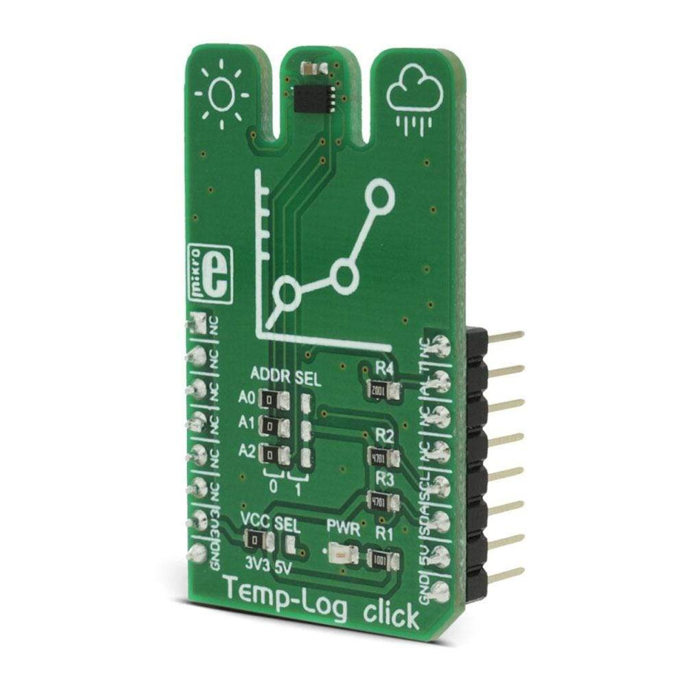
The Temp-Log Click Board™ is a precise ambient temperature measurement device, equipped with 8Kbit (1024 bytes) of EEPROM memory, which can be used to permanently store system configuration or log application specific or user preference data. This Click Board™ covers a range of temperatures from -55°C to +125C with the highest accuracy of 0.5°C, in the range of 0°C to 85°C. The device can also send an ALERT signal to the INT pin of the mikroBUS every time programmed temperature thresholds are reached.
Downloads
The Temp-Log Click Board™ is a precise ambient temperature measurement device, equipped with 8Kbit (1024 bytes) of EEPROM memory, which can be used to permanently store system configuration or log application specific or user preference data. This click covers a range of temperatures from -55°C to +125°C with the highest accuracy of ±0.5°C, in the range of 0°C to 85°C. The device can also send an ALERT signal to the INT pin of the mikroBUS™ every time programmed temperature thresholds are reached.
Besides the EEPROM, the device also contains non-volatile configuration register, which is copied to the main configuration register after every restart of the device. This allows for near-autonomous operation of the device, without the need to initialize the sensor configuration parameters after every power cycle. These features make the Temp-Log click a perfect choice for temperature measurement in a wide variety of communication, consumer, computer, industrial and similar applications, with an addition of up to 8Kbit of user data storage space.
How Does The Temp-Log Click Board™ Work?
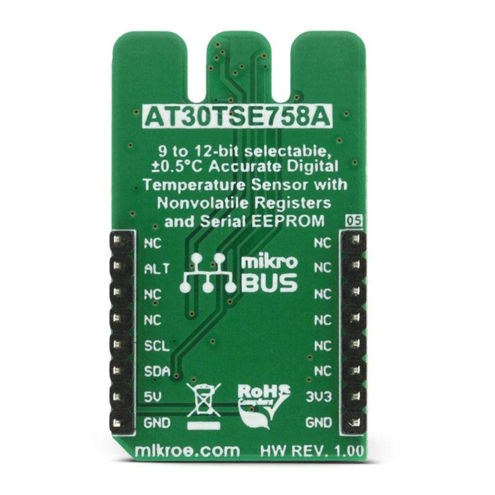
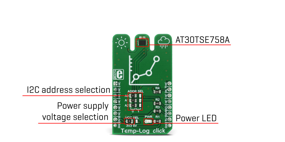
The main active component used on this click is the AT30TSE758A, a 9 to 12bit, ±0.5°C accurate digital temperature sensor with non-volatile registers and integrated serial EEPROM, from Microchip. The AT30TSE758A utilizes a band-gap type temperature sensor with an internal sigma-delta ADC to measure and convert the temperature. The internal ADC can be configured to work with the resolution of 9, 10, 11 or 12 bits. This directly affects the size of the temperature measurement steps. However, it should be noted that the higher resolution results in longer conversion times. The measured temperature is calibrated in degrees Celsius.
The AT30TSE758A sensor uses the I2C bus for the communication with the MCU. This sensor has 7 data registers, which are used to access all of the functions of this device. After initializing the I2C communication with the START condition from the master, a valid device address is expected. This thermal sensor uses 1001AAA as the 7bit I2C address, where "AAA" corresponds to the hard-wired A2 to A0 address pins. Those pins can be set to a HIGH or a LOW logic state by switching the onboard SMD jumpers, labelled as A0, A1, and A2. After the correct address has been received by the sensor, it will respond with the ACK and it is ready to accept the address of one of the seven available 16bit registers.
The 16bit temperature register holds the converted thermal data in MSB/LSB format and is available for reading at every moment; the thermal conversion is performed in the background, and if there is no active READ task over the thermal register, the newly converted temperature data is placed in this register. If there is an active READ task being performed, the converted thermal data will be withheld, until the reading process is completed.
The AT30TSE758A sensor is made with the power saving in mind. When the shutdown mode is engaged, the power consumption is minimal and most of the device sections are not consuming any power. The ONE SHOT function allows to wake up the device, take one measurement, update the registers and go into shutdown mode again. This is accomplished by the OS bit in the config register. Setting this bit as 1 while the device is in the shutdown mode will perform one reading cycle as described above. This allows for a minimum power consumption.
The 16bit configuration register is used to configure all the working parameters of the sensor: mode (one-shot mode, normal and shutdown mode), conversion resolution, the polarity of the ALERT pin, ALERT mode, non-volatile memory busy status and so on. There is also a copy of this register in the non-volatile memory, which can be independently changed. After the power on, the content of the non-volatile config register will be copied to its volatile counterpart. The non-volatile version of the configuration register contains additional bits for the permanent lock-down and config lock, used to prevent further changes of the configuration parameters.
Also, there are two more 16bit registers used to set the high and the low temperature threshold, which also have their non-volatile copies. Depending on the ALERT mode bit in the config register, the temperature threshold values in these registers will be used to trigger an event on the ALERT pin, routed to the mikroBUS™ INT pin. This pin is pulled HIGH on this click so it is a good idea to configure it as active LOW, by using the polarity bit in the config register.
The 8Kbit EEPROM section of the AT30TSE758A acts as an additional serial device, with its own I2C slave address. The 7bit I2C address of the serial EEPROM is 1010APP, where "A" corresponds to the status of the A2 address pin. The last two "P" characters correspond to the memory page bits P1 and P0. The remaining two address pin states (A0 and A1) are not required to match when addressing the EEPROM. These bits, along with the word address byte transmitted via the I2C, now comprise the 10bit address field required to map all of the 1024 bytes available on this device. The EEPROM itself contains 16 bytes per page and has 64 pages in an array.
MikroElektronika provides libraries and functions which simplify working with this device. For more detailed information on the functionality of this device, it is always a good idea to consult the AT30TSE758A datasheet.
The Temp-Log Click Board™ is capable of working with both 3.3V and 5V systems. The desired operational voltage can be selected by the VCC SEL SMD jumper. SCL and SDA lines are both pulled HIGH by the onboard resistors, so the Temp-Log click is ready to be used right out of the box.
SPECIFICATIONS
| Type | Temperature & humidity,Temperature Logging |
| Applications | The Temp-Log Click Board™ can be used for the temperature measurement in a wide variety of communication, consumer, computer, industrial and similar applications, where accurate ambient thermal measurement with a simple data logging is required. |
| On-board modules | AT30TSE758A, a 9 to 12bit, ±0.5°C accurate digital temperature sensor with non-volatile registers and integrated serial EEPROM, from Microchip. |
| Key Features | An accurate 12bit thermal sensor with non-volatile registers and 8Kbit of EEPROM for storing user data. Optimized for low power performance and intelligent data management. |
| Interface | I2C |
| Compatibility | mikroBUS |
| Click board size | M (42.9 x 25.4 mm) |
| Input Voltage | 3.3V or 5V |
PINOUT DIAGRAM
This table shows how the pinout on Temp-Log click corresponds to the pinout on the mikroBUS™ socket (the latter shown in the two middle columns).
| Notes | Pin | Pin | Notes | ||||
|---|---|---|---|---|---|---|---|
| NC | 1 | AN | PWM | 16 | NC | ||
| NC | 2 | RST | INT | 15 | ALT | Alert | |
| NC | 3 | CS | RX | 14 | NC | ||
| NC | 4 | SCK | TX | 13 | NC | ||
| NC | 5 | MISO | SCL | 12 | SCL | I2C Clock | |
| NC | 6 | MOSI | SDA | 11 | SDA | I2C Data | |
| Power Supply | +3V3 | 7 | 3.3V | 5V | 10 | +5V | Power Supply |
| Ground | GND | 8 | GND | GND | 9 | GND | Ground |
TEMP-LOG CLICK MAXIMUM RATINGS
| Description | Min | Typ | Max | Unit |
|---|---|---|---|---|
| Temperature measurement range | -55 | +125 | °C | |
| Temperature measurement accuracy | ±0.5 | ±3 | °C | |
| Temperature measurement conversion resolution | 9 | 12 | bits | |
| I2C clock speed | 1 | 4000 | kHz |
ONBOARD SETTINGS AND INDICATORS
| Label | Name | Default | Description |
|---|---|---|---|
| LD1 | PWR | Power LED indicator | |
| JP1 | A0 | Left | I2C address bit 0 selection: left position '0', right position '1' |
| JP2 | A1 | Left | I2C address bit 1 selection: left position '0', right position '1' |
| JP3 | A2 | Left | I2C address bit 2 selection: left position '0', right position '1' |
| JP4 | VCC SEL | Left | Power supply voltage selection, left position 3V3, right position 5V |
| General Information | |
|---|---|
Part Number (SKU) |
MIKROE-2886
|
Manufacturer |
|
| Physical and Mechanical | |
Weight |
0.017 kg
|
| Other | |
EAN |
8606018712243
|
Frequently Asked Questions
Have a Question?
Be the first to ask a question about this.