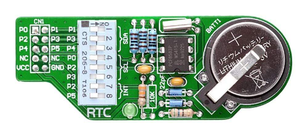
Overview
Introduce the functionality of a real-time clock and calendar in the design with the RTC Board. This additional board includes a PCF8583 clock and calendar chip based on 240 x 8-bit RAM organized as 256 words by 8 bits. Driven by a battery cell (not the normal power supply), the operation of the real-time clock is enabled even when the MCU
Downloads
IC/Module: PCF8583 Clock and Calendar with 240 x 8-bit RAM
The PCF8583 is a real-time clock and calendar IC designed to keep track of the current time and date even when the microcontroller is turned off. Based on a 2048 bit static CMOS RAM, it is capable of generating interrupts as well as provide timer and alarm functions. As each data byte is written or read, the built-in word address register is automatically incremented. The chip comprises of a 256 by 8 bit RAM with an 8 bit auto-increment address register, an on-chip 32.768 kHz oscillator circuit, a frequency divider, a serial two-line bidirectional I2C-bus interface, and a Power-On Reset (POR) circuit.
Counter Function Modes
When the control and status register is programmed, a 32.768 kHz clock mode, a 50 Hz clock mode or an event-counter mode can be selected.
Alarm Function Modes
The alarm control register is activated by setting the alarm enable bit of the control and status register. It enables user to set a dated alarm, a daily alarm, a weekday alarm, or a timer alarm may be programmed by setting the alarm control register.
| General Information | |
|---|---|
Part Number (SKU) |
MIKROE-87
|
Manufacturer |
|
| Physical and Mechanical | |
Weight |
0.1 kg
|
| Other | |
Warranty |
|
HS Code Customs Tariff code
|
|
EAN |
8606015072043
|
Frequently Asked Questions
Have a Question?
Be the first to ask a question about this.

