


Mikroelektronika d.o.o.
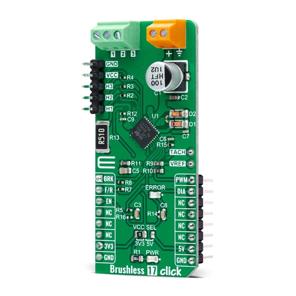
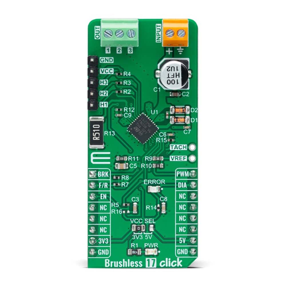
Brushless 17 Click Board™
Brushless 17 Click Board™
SKU: MIKROE-5000
Couldn't load pickup availability


Key Features
Overview
The Brushless 17 Click Board™ is a compact add-on board suitable for controlling brushless DC (BLDC) motors with any MCU. This board features the L6229Q, DMOS fully integrated three-phase BLDC motor driver with overcurrent protection from STMicroelectronics. This motor driver combines isolated DMOS power transistors with CMOS and bipolar circuits on the same chip, realized in BCD (Bipolar-CMOS-DMOS) multipower technology. It includes all the circuitry for a three-phase BLDC motor drive, including a three-phase DMOS bridge, a constant off-time PWM current controller, and the decoding logic for single-ended hall sensors that generate the required sequence for the power stage. This Click board™ makes the perfect solution for driving three-phase brushless DC motors with currents up to 1A DC.
The Brushless 17 Click Board™ is supported by a mikroSDK compliant library, which includes functions that simplify software development. This Click board™ comes as a fully tested product, ready to be used on a system equipped with the mikroBUS™ socket.
Downloads
How Does The Brushless 17 Click Board™ Work?
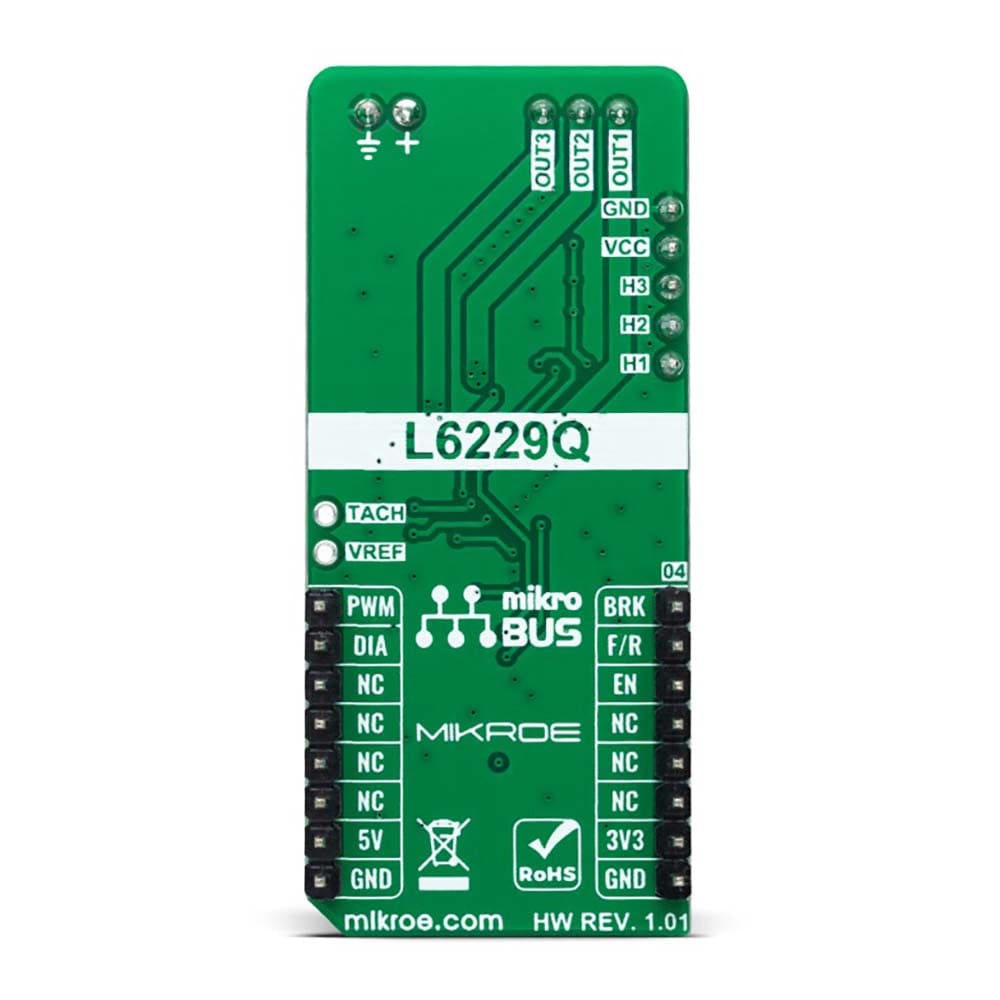
The Brushless 17 Click Board™ as its foundation uses the L6229Q, DMOS fully integrated three-phase BLDC motor driver with overcurrent protection from STMicroelectronics. It combines a three-phase bridge, which consists of 6 power MOSFETs. Switching patterns are generated by the PWM current controller and the hall-effect sensor decoding logic, which represents a combinatory logic that provides the appropriate driving signals for the three-phase bridge outputs (1, 2, and 3). Drive signals are based on the signals coming from the three hall sensors, H1, H2, and H3, applicable on the upper-left header reserved for Hall sensor connection. These hall sensors detect rotor position in a 3-phase BLDC motor.
.jpg)
The L6229Q can perform PWM current control, with analog reference voltage provided at its VREF pin. This control can be achieved by using a PWM signal from the mikroBUS™ socket or applying an external reference voltage. When using PWM signal from mikroBUS™, leave R10 resistor populated. This is a straightforward way of obtaining a variable voltage without using a DAC, using a low-pass filter to filter the PWM signal. Alternatively, a fixed reference voltage can also be obtained through an external voltage supply on the VREF pin. This board also provides a tachometer function, a TACH output signal, which can be used to implement a simple frequency-to-voltage converter (speed loop control).
The Brushless 17 Click Board™ communicates with MCU using several GPIO pins. The Enable pin, labelled as EN and routed to the CS pin of the mikroBUS™ socket, optimizes power consumption used for power ON/OFF purposes (performs Start and Stop controls of the motor operation), while AN pin labelled as BRK allows users to implement the brake function. The F/R pin, routed on the RST pin of the mikroBUS™ socket, is used to select the direction of motor rotation (forward/reverse). Besides, it is possible to detect operational irregularities, such as overcurrent and thermal detection, where an indication of such a condition is performed using the red LED indicator labelled as ERROR routed on the INT pin of the mikroBUS™ socket, labelled as DIA.
This board supports an external power supply for the motor, which can be connected to the input terminal labelled as INPUT and should be within the range of 8V to 52V, while the BLDC motor coils can be connected to the terminals labelled as 1, 2, and 3.
The Brushless 17 Click Board™ can operate with both 3.3V and 5V logic voltage levels selected via the VCC SEL jumper. This way, it is allowed for both 3.3V and 5V capable MCUs to use the communication lines properly. However, the Click board™ comes equipped with a library containing easy-to-use functions and an example code that can be used, as a reference, for further development.
SPECIFICATIONS
| Type | Brushless |
| Applications | The Brushless 17 Click Board™ can be used driving three-phase brushless DC motors with currents up to 1A DC |
| On-board modules | L6229Q - DMOS fully integrated three-phase BLDC motor driver with overcurrent protection from STMicroelectronics |
| Key Features | Low power consumption, overcurrent detection and protection, diagnostic output, PWM current controller, brake function, and more |
| Interface | GPIO,PWM |
| Compatibility | mikroBUS |
| Click board size | L (57.15 x 25.4 mm) |
| Input Voltage | 3.3V or 5V,External |
PINOUT DIAGRAM
This table shows how the pinout of the Brushless 17 Click Board™ corresponds to the pinout on the mikroBUS™ socket (the latter shown in the two middle columns).
| Notes | Pin | Pin | Notes | ||||
|---|---|---|---|---|---|---|---|
| Brake | BRK | 1 | AN | PWM | 16 | PWM | PWM Signal |
| Forward/Reverse Direction | F/R | 2 | RST | INT | 15 | DIA | Fault Interrupt |
| Enable | EN | 3 | CS | RX | 14 | NC | |
| NC | 4 | SCK | TX | 13 | NC | ||
| NC | 5 | MISO | SCL | 12 | NC | ||
| NC | 6 | MOSI | SDA | 11 | NC | ||
| Power Supply | 3.3V | 7 | 3.3V | 5V | 10 | 5V | Power Supply |
| Ground | GND | 8 | GND | GND | 9 | GND | Ground |
ONBOARD SETTINGS AND INDICATORS
| Label | Name | Default | Description |
|---|---|---|---|
| LD1 | PWR | - | Power LED Indicator |
| LD2 | ERROR | - | Fault Condition LED Indicator |
| J1 | - | Populated | Hall Sensor Connection Header |
| J2 | - | Unpopulated | Tachometer for Speed Contol Loop pin / External Reference Voltage for PWM Current Control |
BRUSHLESS 17 CLICK ELECTRICAL SPECIFICATIONS
| Description | Min | Typ | Max | Unit |
|---|---|---|---|---|
| Supply Voltage VCC | 3.3 | - | 5 | V |
| External Supply Voltage INPUT | 8 | - | 52 | V |
| Maximum Output Current | - | - | 1.4 | A |
| Operating Temperature Range | -25 | +25 | +120 | °C |
| General Information | |
|---|---|
Part Number (SKU) |
MIKROE-5000
|
Manufacturer |
|
| Physical and Mechanical | |
Weight |
0.02 kg
|
| Other | |
EAN |
8606027388620
|
Frequently Asked Questions
Have a Question?
Be the first to ask a question about this.