


Mikroelektronika d.o.o.
Brushless 9 Click Board™
Brushless 9 Click Board™
SKU: MIKROE-4387
Couldn't load pickup availability
Overview
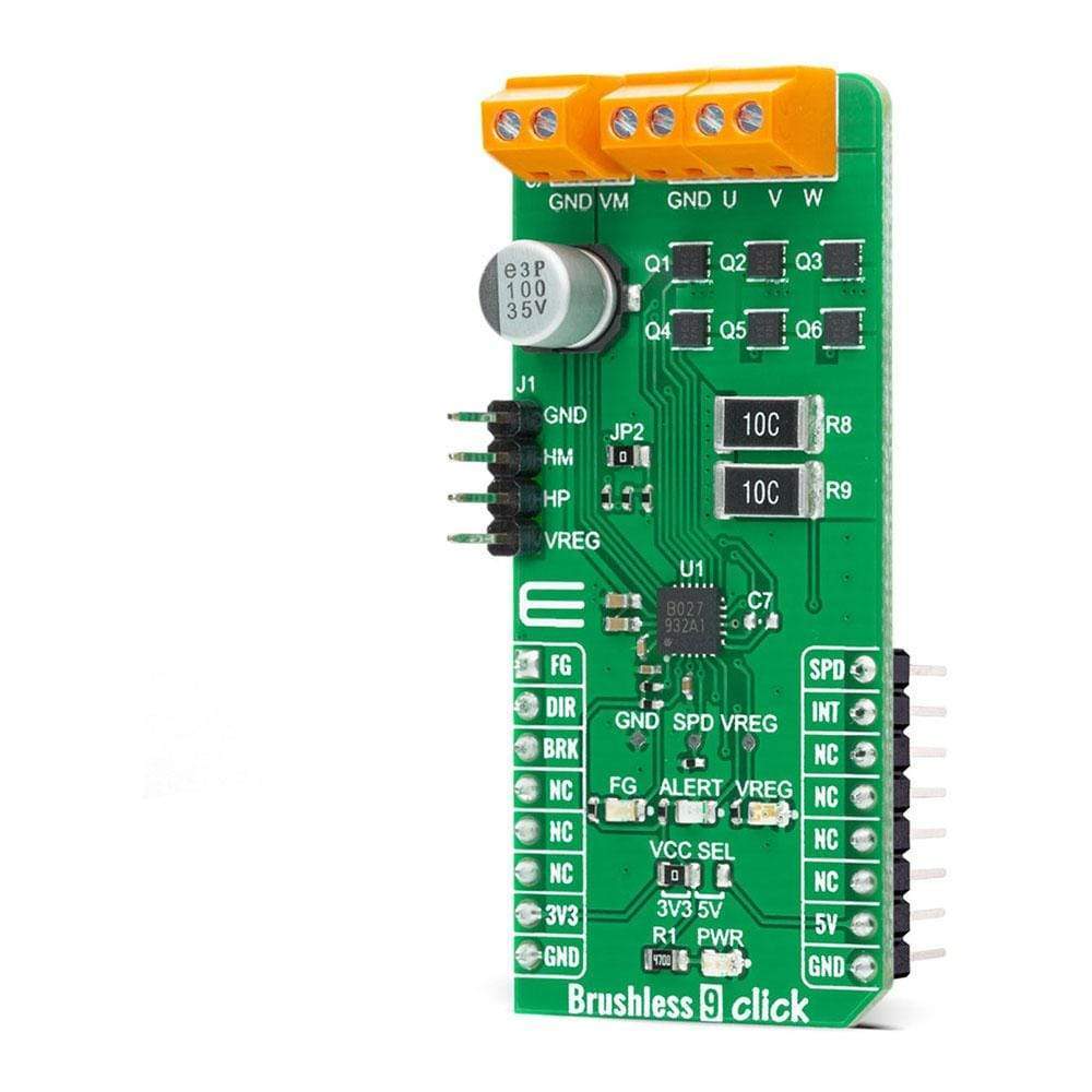
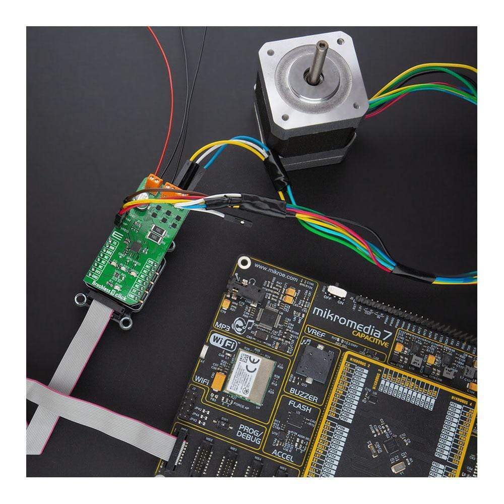
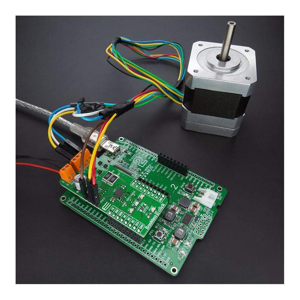
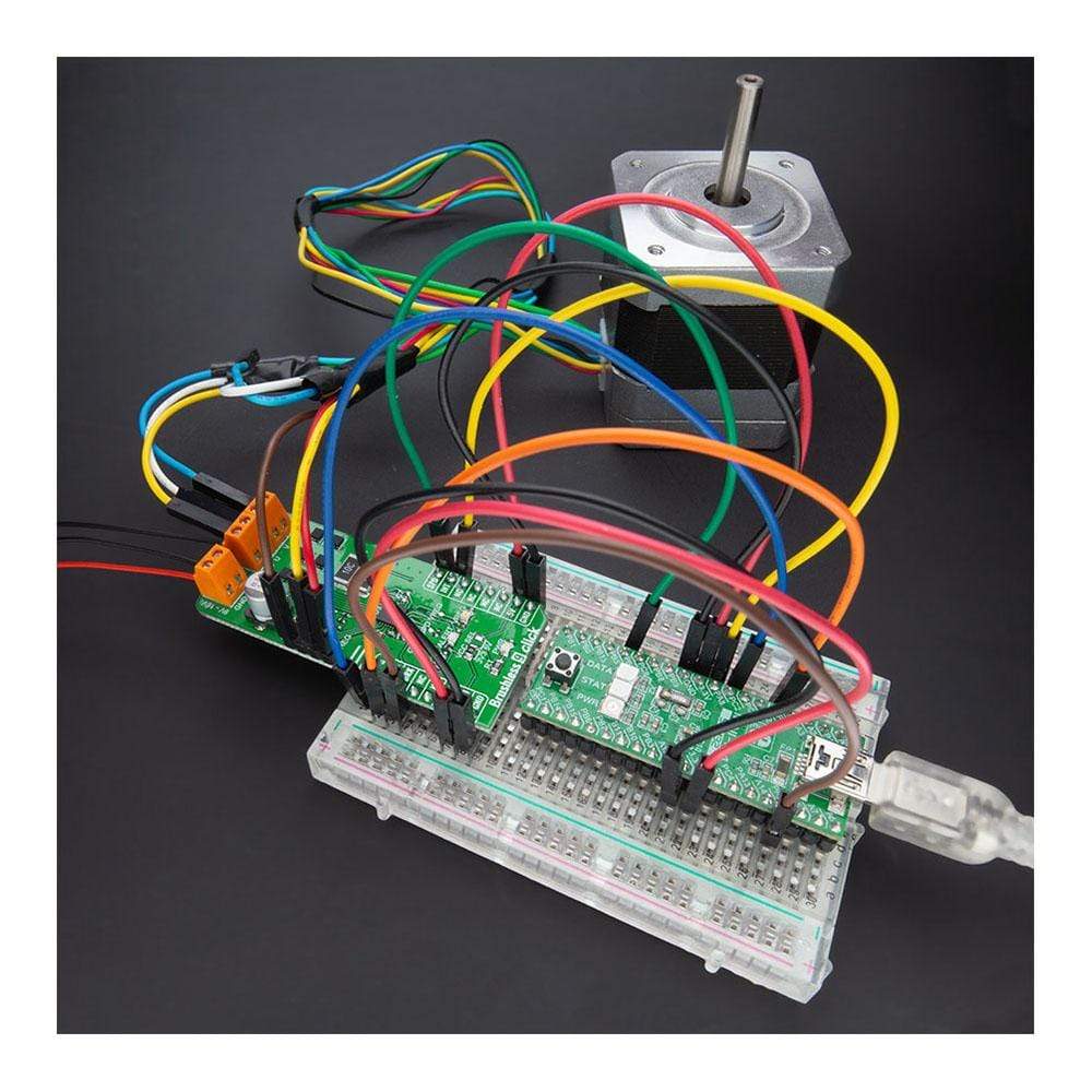
The Brushless 9 Click Board™ is a compact add-on board that controls BLDC motors with any MCU. This board features the TC78B027FTG, a 1-Hall sine-wave PWM controller for three-phase brushless DC motors from Toshiba Semiconductor. It simplifies the motor selection by using only one Hall sensor input that can be used with either a single Hall sensor motor or the more conventional 3 Hall sensor motors. Besides, it offers energy-saving and quiet motor operation, incorporating non-volatile memory and a closed-loop speed control function. This Click Board™ provides optimum operating efficiency in applications such as high-velocity server fans, blowers, and pumps.
The Brushless 9 Click Board™ is supported by a mikroSDK compliant library, which includes functions that simplify software development. This Click Board™ comes as a fully tested product, ready to be used on a system equipped with the mikroBUS™ socket.
Downloads
How Does The Brushless 9 Click Board™ Work?
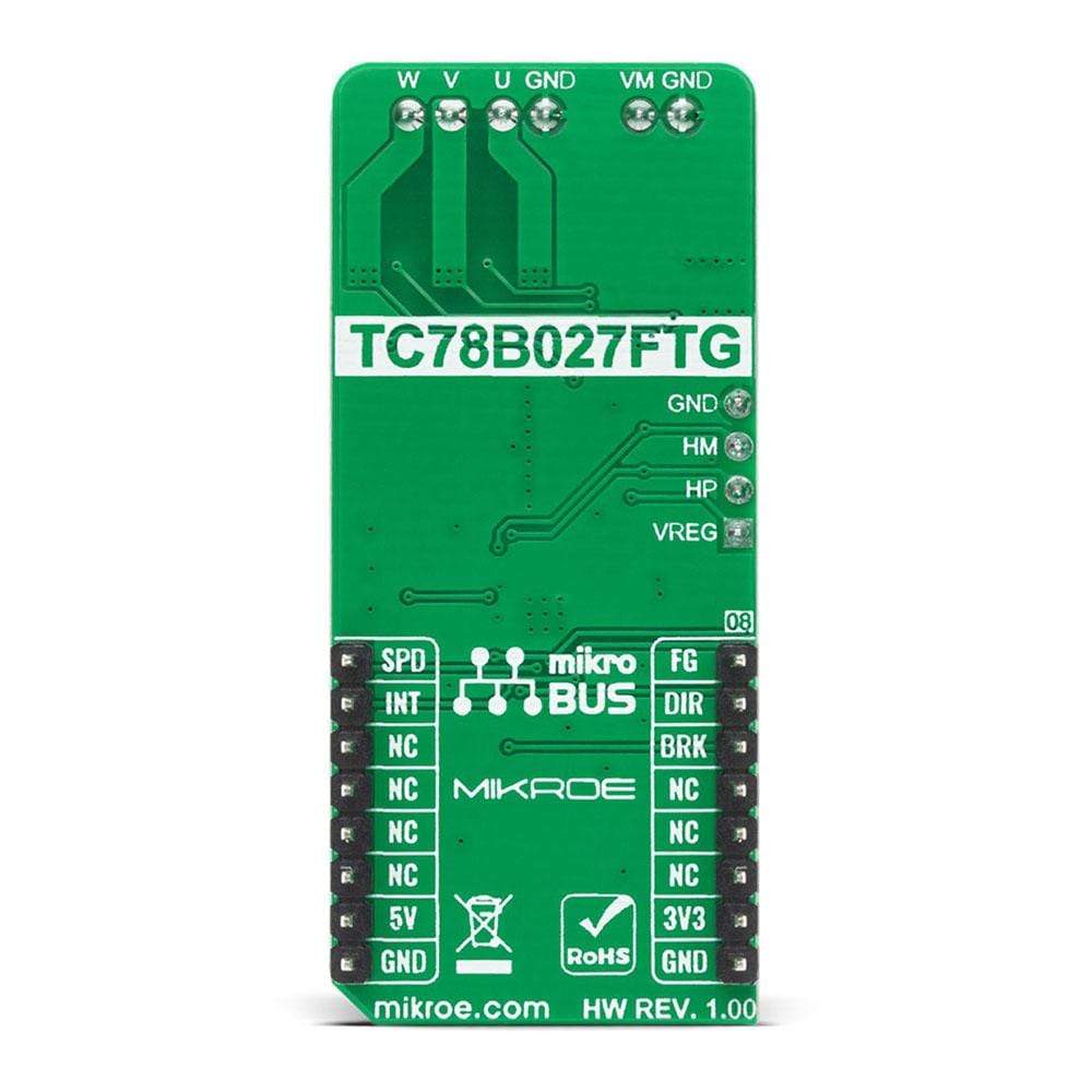
The Brushless 9 Click Board™ is based on the TC78B027FTG, a 1-Hall sine-wave PWM controller for three-phase brushless DC motors from Toshiba Semiconductor. The TC78B027FTG simplifies the motor selection by using only one Hall sensor input that can be used with either a single Hall sensor motor or the more conventional 3 Hall sensor motors. It can be operated by 1-Hall sine-wave commutation and 1-Hall 150° commutation, which can be switched by register configuration. Also, a closed-loop speed control function is implemented without using an external MCU. The closed-loop control function regulates motor rotational speed fluctuations caused by changes in power supply voltage and load. The TC78B027FTG also has some protection features such as thermal shutdown, overvoltage and overcurrent protection, lock detection, and many more.

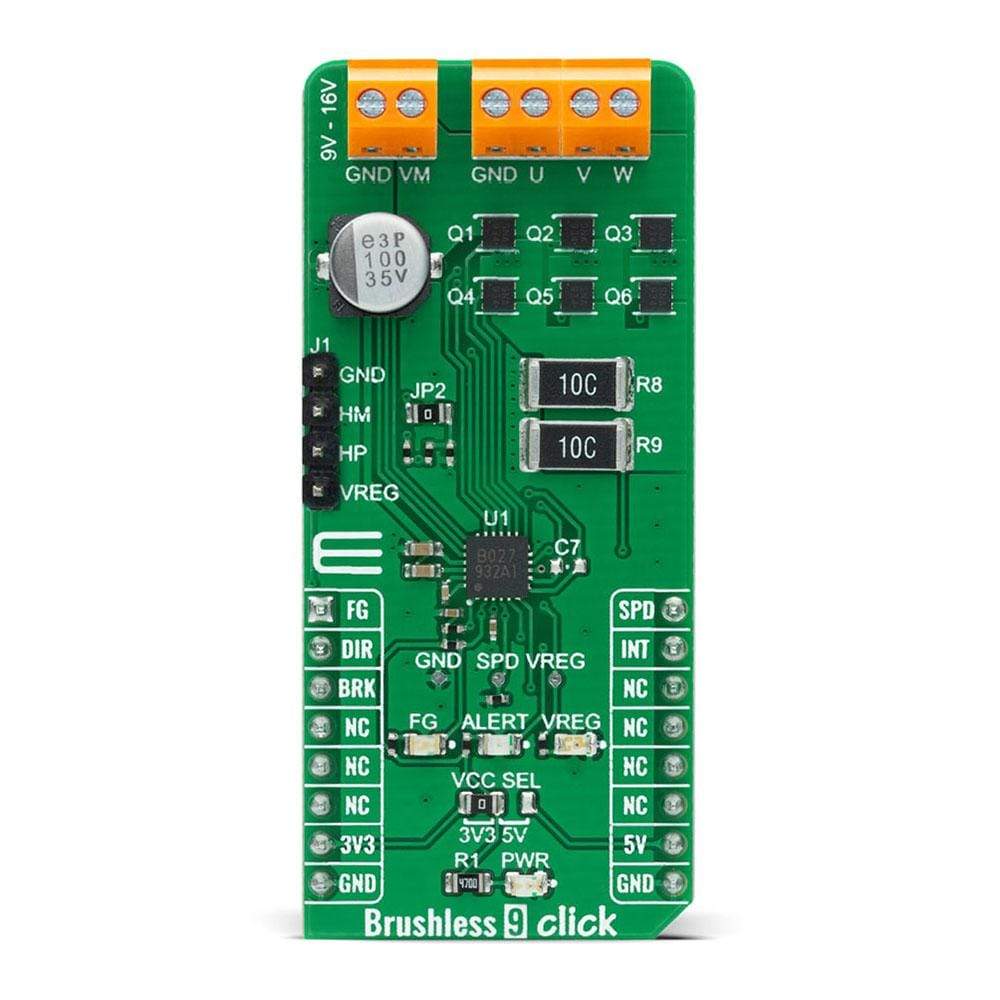
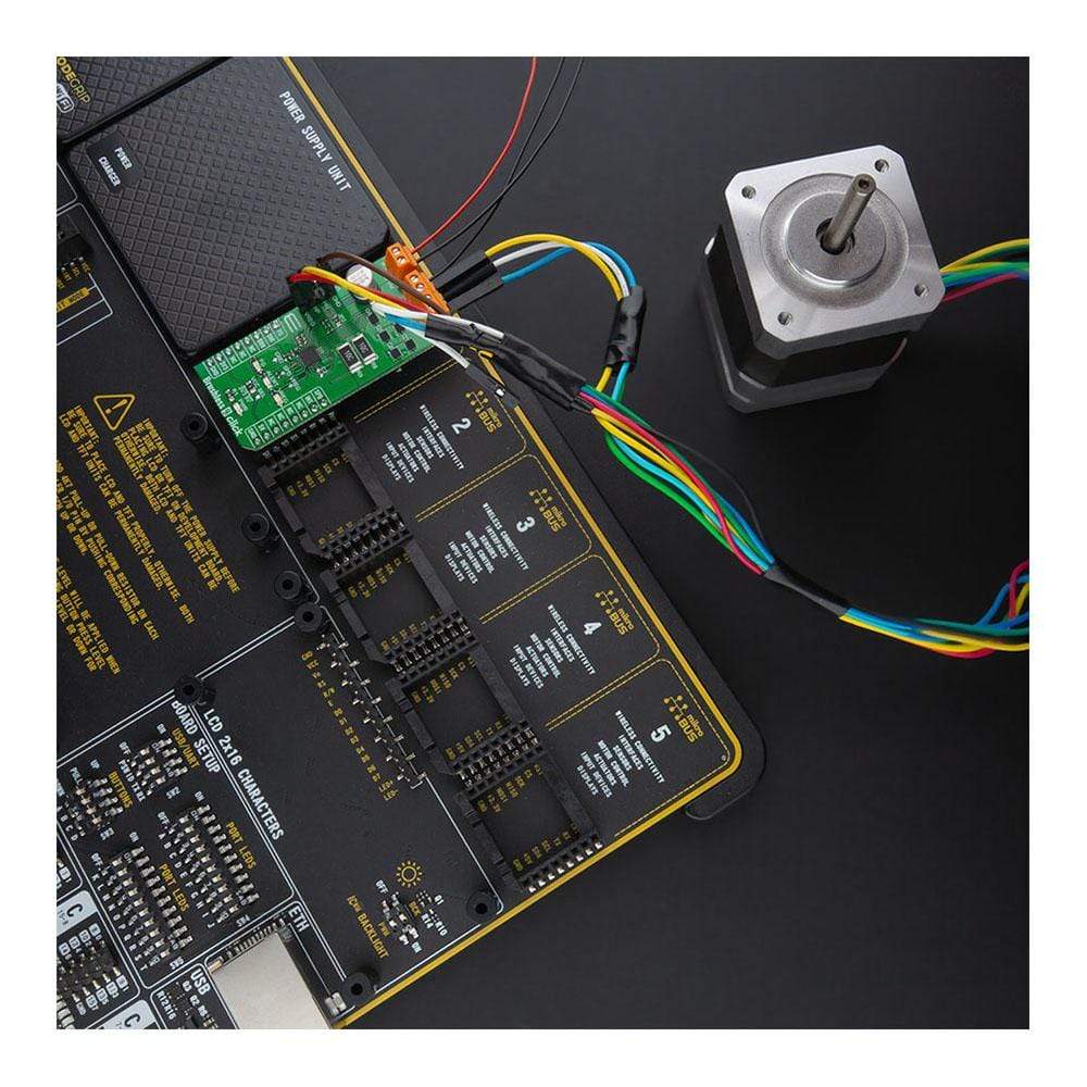
For Normal operation, it is necessary to apply the voltage in the range from 9V to 16V to the external connector labeled as VM and to connect Hall signals from the BLDC motor through the J1 header on the left side of the board. The operation moves to the Standby mode when a zero cross of the Hall signal is not detected for a lock detection period after the voltage of 1V or less is applied to the SPD pin. In the Standby mode, the power consumption is reduced by powering off its internal 5V regulator. The TC78B027FTG also drives six external N-CH MOSFETs, the SSM6K513NU from Toshiba Semiconductor, that run the connected Brushless DC Motor. For this type of application, more precisely for Brushless Click boards that require BLDC Motor with Hall Sensor for their work, Mikroe offers its users just one such motor, whose offer you can find here.
The Brushless 9 Click Board™ communicates with MCU using several GPIO pins. The DIR pin, routed on the RST pin of the mikroBUS™ socket, is used to select the direction of motor rotation, while the motor braking function is available on the CS pin of the mikroBUS™ socket labeled as BRK. The TC78B027FTG has several braking functions: Motor OFF, Short Brake, Reverse Brake, Mild Brake. On the other hand, functions such as Motor START, Motor STOP, and Rotation Speed can be set using the SPD pin routed on the PWM pin of the mikroBUS™ socket, where the PWM duty signal and the polarity of this signal can be configured by the register.
If any of the previously mentioned critical conditions (such as over current, over temperature, motor lock) occur, the TC78B027FTG will signal such a phenomenon using an LED diode labeled as ALERT connected to the interrupt pin marked as INT on the mikroBUS™ socket. Besides, it is possible to detect the occurrence of motor lock events where the indication of such a condition is performed using the LED indicator labeled as FG routed on the AN pin of the mikroBUS™ socket.
NOTE: Pins such as FG, SPD, and INT can also be used as serial interface pins, where FG can be used for SDI or SIO signal, SPD for SCK signal, while INT can be used as SDO signal in case of 3-wire SPI communication. In case the SDO line is not used, INT retains its ALERT function.
The Brushless 9 Click Board™ is designed to be operated with both 3.3V and 5V logic voltage levels that can be selected via VCC SEL jumper. This allows for both 3.3V and 5V capable MCUs to use communication lines properly.
SPECIFICATIONS
| Type | Brushless |
| Applications | Can be used in applications such as high-velocity server fans, blowers, and pumps. |
| On-board modules | The Brushless 9 Click Board™ is based on the TC78B027FTG, a 1-Hall sine-wave PWM controller for three-phase brushless DC motors from Toshiba Semiconductor. |
| Key Features | 1-Hall sine-wave PWM drive, closed loop speed control, output RPM information, protection features, and more. |
| Interface | GPIO |
| Compatibility | mikroBUS |
| Click board size | L (57.15 x 25.4 mm) |
| Input Voltage | 3.3V or 5V |
PINOUT DIAGRAM
This table shows how the pinout on Brushless 9 Click corresponds to the pinout on the mikroBUS™ socket (the latter shown in the two middle columns).
| Notes | Pin | Pin | Notes | ||||
|---|---|---|---|---|---|---|---|
| Hall Signal Rotation Pulse/Motor Lock Detection | FG | 1 | AN | PWM | 16 | SPD | Motor Control/Rotation Speed |
| Forward/Reverse Direction | DIR | 2 | RST | INT | 15 | INT | Interrupt |
| Motor Brake | BRK | 3 | CS | RX | 14 | NC | |
| NC | 4 | SCK | TX | 13 | NC | ||
| NC | 5 | MISO | SCL | 12 | NC | ||
| NC | 6 | MOSI | SDA | 11 | NC | ||
| Power Supply | 3.3V | 7 | 3.3V | 5V | 10 | 5V | Power Supply |
| Ground | GND | 8 | GND | GND | 9 | GND | Ground |
ONBOARD SETTINGS AND INDICATORS
| Label | Name | Default | Description |
|---|---|---|---|
| LD1 | PWR | - | Power LED Indicator |
| LD2 | VREG | - | VREG LED Indicator |
| LD3 | ALERT | - | ALERT LED Indicator |
| LD4 | FG | - | FG LED Indicator |
| JP1 | VCC SEL | Left | Power Supply Voltage Selection 3V3/5V: Left position 3V3, Right position 5V |
| J1 | HALL | Populated | Hall Sensor Input Pins |
BRUSHLESS 9 CLICK ELECTRICAL SPECIFICATIONS
| Description | Min | Typ | Max | Unit |
|---|---|---|---|---|
| Supply Voltage | 9 | - | 16 | V |
| Maximum Output Voltage | - | - | 30 | V |
| Maximum Output Current | - | - | 15 | A |
| Power Dissipation | - | - | 2.5 | W |
| Operating Temperature Range | -40 | - | +105 | °C |
| General Information | |
|---|---|
Part Number (SKU) |
MIKROE-4387
|
Manufacturer |
|
| Physical and Mechanical | |
Weight |
0.022 kg
|
| Other | |
EAN |
8606027381478
|
Frequently Asked Questions
Have a Question?
Be the first to ask a question about this.