Overview
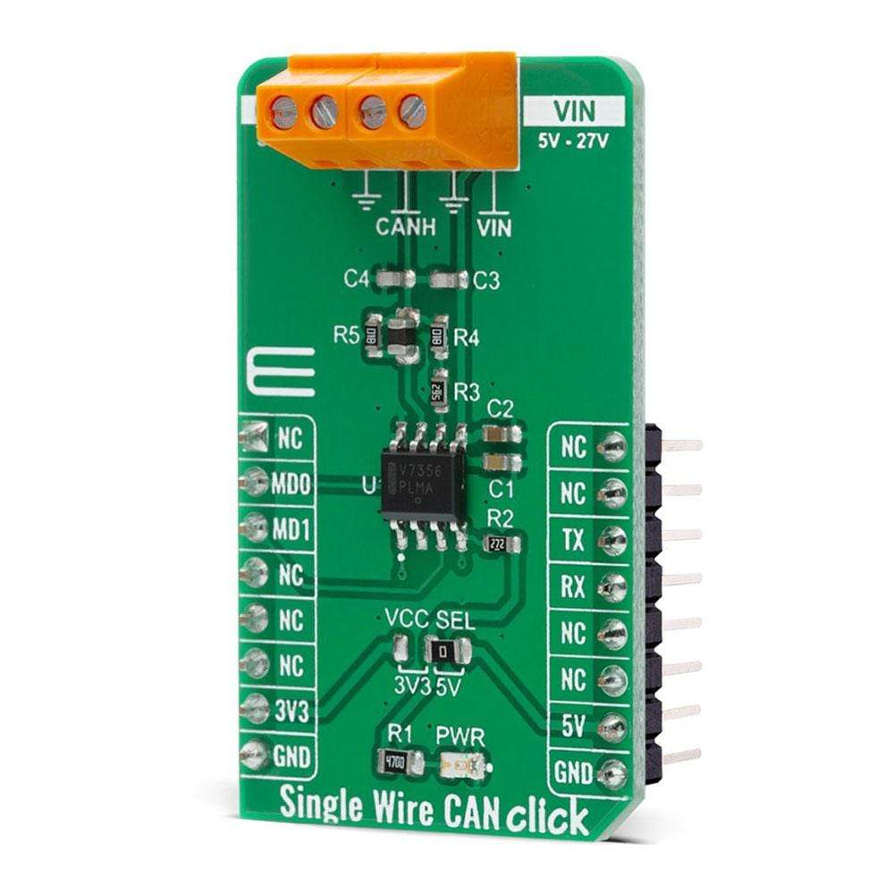
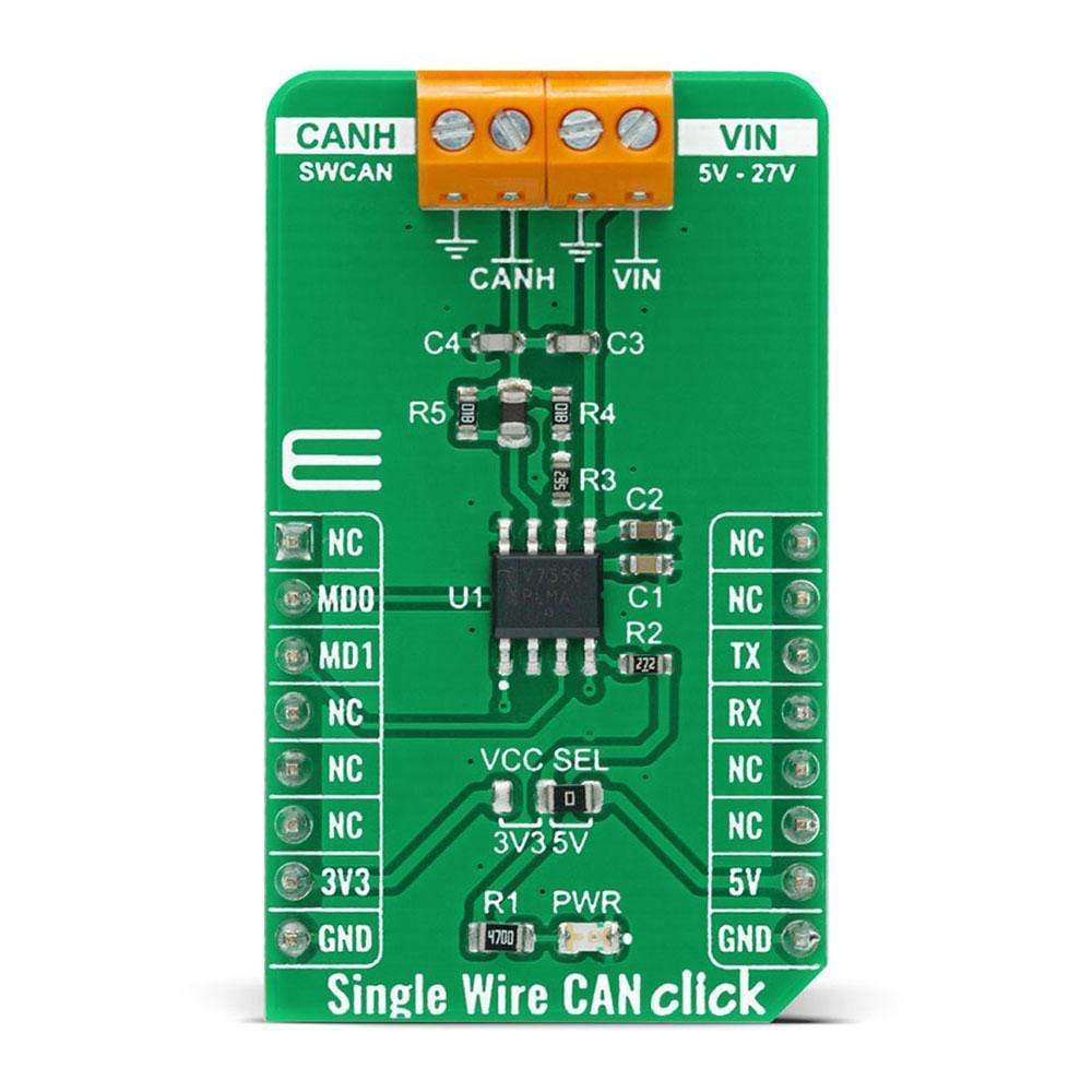
The Single Wire CAN Click Board™ is a compact add-on board that contains an IC for a single wire data link capable of operating with various protocols such as the Controller Area Network (CAN). This board features the NCV7356D1R2G, Single Wire CAN transceiver from ON Semiconductor, which operates from a supply voltage from 5V to 27V with bus speed up to 40 kbps. It supports many additional features like an under-voltage lockout, a timeout for faulty blocked input signals, output blanking time in case of bus ringing, and a very low sleep mode current. This Click Board™ can be used in industrial equipment, in-vehicle, and industrial networking, and in applications where the high data rate is not required and a lower data rate can achieve cost reductions.
The Single Wire CAN Click is supported by a mikroSDK compliant library, which includes functions that simplify software development. This Click Board™ comes as a fully tested product, ready to be used on a system equipped with the mikroBUS™ socket.
Downloads
How Does The Single Wire CAN Click Board™ Work?
The Single Wire CAN Click Board™ is based on the NCV7356D1R2G, a Single Wire CAN transceiver from ON Semiconductor, which operates from a supply voltage from 5V to 27V with a bus speed up to 40 kbps. It can access several modes such as Normal Mode with reduced dominant output voltage and reduced receiver input voltage, High-Speed, High Voltage Wake-Up, or Sleep Mode. The transmission bit rate in Normal communication is 33 Kbits/s, while a typical bit rate of 83 kbit/s is recommended for High-Speed communication. In Normal Transmission Mode, the Single Wire CAN Click supports controlled waveform rise and overshoot times, while the High−Speed Mode is only intended to be operational when the bus is attached to an off−board service node.
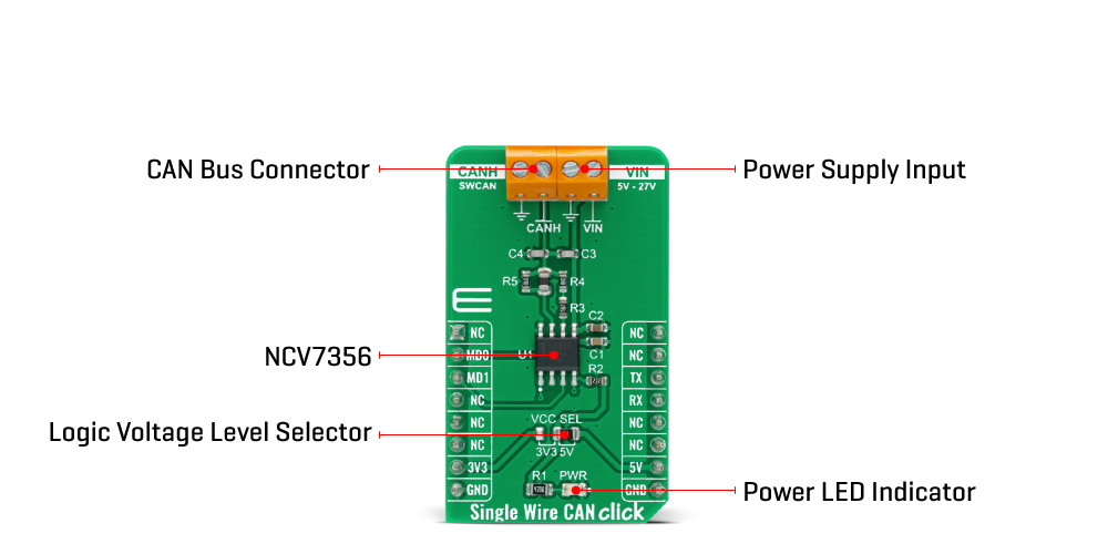
The Single Wire CAN Click Board™ pin CANH is composed of a pull−up amplifier for driving this Click board™. The minimum output driver capability is 50 mA, but output shorts to the ground can reach 350mA. Normal CANH output voltage is between 4.4 V and 5.1 V. These amplitudes increase to between 9.9 V and 12.5 V for system selection in Wake−Up Mode. The bus Wake−Up from Sleep Input Voltage Threshold is between 6.6 V and 7.9 V, but to maintain normal communication, the threshold is 2.1 V. The CANH pin can also act as a bus read amplifier.
The NCV7356D1R2G communicates with MCU using the UART interface at 9600 bps with commonly used UART RX and TX pins. It possesses additional functionality such as Operational Mode Selection MODE 0 and MODE 1 routed at RST and CS pins of the mikroBUS™, on whose selected logical states one of the four possible operational modes can be selected. The transceiver provides a weak internal pulldown current on each of these pins which causes the transceiver on default to enters to sleep mode when they are not driven. Single Wire CAN Click can also re-enter the Sleep Mode if there is no mode change within typically 250 ms.
The Single Wire CAN Click Board™ communicates with MCU using the UART interface for the data transfer. The onboard SMD jumper labelled as VCC SEL allows logic level voltage selection for interfacing with both 3.3V and 5V MCUs. More information about the NCV7356D1R2G's functionality, electrical specifications, and typical performance can be found in the attached datasheet. However, the Click board™ comes equipped with a library that contains easy to use functions and a usage example that may be used as a reference for the development.
SPECIFICATIONS
| Type | CAN |
| Applications | Can be used in industrial equipment, and applications such as in-vehicle and industrial networking. |
| On-board modules | The Single Wire CAN Click Board™ is based on the NCV7356D1R2G, a Single Wire CAN transceiver from ON Semiconductor, which operates from a supply voltage from 5V to 27V with a bus speed up to 40 kbps. |
| Key Features | Low power consumption, fully integrated receiver filter, loss of ground protection, undervoltage lockout, and more. |
| Interface | GPIO,UART |
| Compatibility | mikroBUS |
| Click board size | M (42.9 x 25.4 mm) |
| Input Voltage | 3.3V or 5V |
PINOUT DIAGRAM
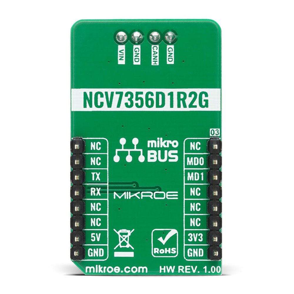
This table shows how the pinout of the Single Wire CAN Click Board™ corresponds to the pinout on the mikroBUS™ socket (the latter shown in the two middle columns).
| Notes | Pin |  |
Pin | Notes | |||
|---|---|---|---|---|---|---|---|
| NC | 1 | AN | PWM | 16 | NC | ||
| Mode Select 0 | MD0 | 2 | RST | INT | 15 | NC | |
| Mode Select 1 | MD1 | 3 | CS | RX | 14 | TX | UART TX |
| NC | 4 | SCK | TX | 13 | RX | UART RX | |
| NC | 5 | MISO | SCL | 12 | NC | ||
| NC | 6 | MOSI | SDA | 11 | NC | ||
| Power Supply | 3.3V | 7 | 3.3V | 5V | 10 | 5V | Power Supply |
| Ground | GND | 8 | GND | GND | 9 | GND | Ground |
ONBOARD SETTINGS AND INDICATORS
| Label | Name | Default | Description |
|---|---|---|---|
| LD1 | PWR | - | Power LED Indicator |
| JP1 | VCC SEL | Right | Power Supply Voltage Selection 3V3/5V: Left position 3V3, Right position 5V |
SINGLE WIRE CAN CLICK ELECTRICAL SPECIFICATIONS
| Description | Min | Typ | Max | Unit |
|---|---|---|---|---|
| Supply Voltage | 5 | - | 27 | V |
| CANH Voltage | -20 | - | +40 | V |
| Maximum Sleep Mode Current | - | - | 60 | μA |
| Operating Temperature Range | -40 | - | +125 | °C |
| General Information | |
|---|---|
Part Number (SKU) |
MIKROE-4225
|
Manufacturer |
|
| Physical and Mechanical | |
Weight |
0.02 kg
|
| Other | |
Country of Origin |
|
HS Code Customs Tariff code
|
|
EAN |
8606027380242
|
Warranty |
|
Frequently Asked Questions
Have a Question?
Be the first to ask a question about this.

