

Mikroelektronika d.o.o.
WiFi 10 Click Board™
WiFi 10 Click Board™
SKU: MIKROE-3432
Couldn't load pickup availability


Key Features
Overview
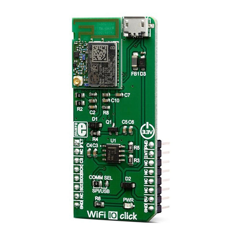
The WiFi 10 Click Board™ offers ultra-low power wireless connectivity for any IoT application. It is based on the SX-ULPAN-SB-2401, an integrated wireless LAN module, compliant with the IEEE802.11a/b/g/n wireless networking protocols, at 2.4GHz. The ULPAN-SB-2401 module comes equipped with a PCB trace antenna, but it also offers a small Hirose U. FL connector allowing an external antenna to be used for improved range. The ULPAN-SB-2401 module supports IPv4, TCP, and UDP transfer protocols. It also supports WPS, WPA, and WPA2 security protocols, allowing a secure connection.
Downloads
The SX-ULPAN-SB-2401 is targeted towards low-power IoT applications. An abundance of integrated WiFi protocols and standards, ability to use an external antenna for improved wireless range, low power consumption, and high data rates, make this Click board™ an ideal solution for the development of applications that require WiFi connectivity and Internet access, with a strong emphasis towards IoT applications.
How Does The WiFi 10 Click Board™ Work?
The WiFi 10 Click Board™ comes equipped with the SX-ULPAN-SB-2401, a low-power wireless LAN module, by Silex technology. The SX-ULPAN-SB-2401 is targeted towards IoT applications, offering a reasonably low power consumption. This module is based on the RF chip labeled as QCA4004X, by Qualcomm. WiFi 10 click uses the SPI communication interface to exchange data with the host MCU. This allows for a very high data rate between the Click board™ and the host MCU (up to 10 Mbps), avoiding bottlenecks when high data rates are required within LAN.
.jpg)
The ULPAN-SB-2401 module supports IPv4, TCP, and UDP transfer protocols, and complies with the IEEE802.11a/b/g/n wireless networking standards, at 2.4GHz. It supports data rates from 1 to 54 Mbps for 802.11b/g, and MCS from 0 to 7, for 802.11n. The SX-ULPAN-SB-2401 module also provides support for WPS, WPA, and WPA2 security protocols, allowing a secure connection.
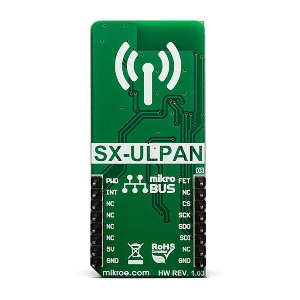
Besides the QCA4004X RF chip itself, the module contains all the supporting circuitry that allows RF signal conditioning, antenna switching, etc. The SX-ULPAN-SB-2401 is equipped with a small trace antenna. However, it allows an external antenna to be connected over a mall Hirose U. FL alternative connector when better signal reception is required. The datasheet of the SX-ULPAN-SB-2401 offers a list of approved and tested external antennas.
The SX-ULPAN-SB-2401 module requires a power supply of 3.3V. Therefore, the Click board™ incorporates an integrated buck (step-down DC-DC) converter, labeled as TPS7A7002 by Texas Instruments. This IC can output up to 3A of current, still maintaining an excellent regulation. Its task is to provide a stable 3.3V power supply, capable of mitigating voltage drops at the input when a high current peak appears (typically at the startup of the device).
The USB connector is used for a firmware update and it is not used during normal operation. The Click board™ is equipped with a small SMD jumper labeled as COM SEL,used to switch the interface to USB when updating the firmware.
The WiFi 10 Click Board™ allows the host MCU to enable/disable the power for the SX-ULPAN-SB-2401 module, by employing a MOSFET. The gate of the MOSFET is routed to the mikroBUS™ AN pin, labeled as FET. By driving this pin to a HIGH logic state, the P channel MOSFET will be disabled and the SX-ULPAN-SB-2401 will be disconnected from the power source. Normally, the MOSFET gate is pulled to the GND by a resistor on the Click board™.
In order to allow the power supply voltage to reach its nominal levels, the Click board™ should be held in a RESET state for more than 25 ms. This can be accomplished by driving the CHIP_PWD_L pin of the module to a LOW logic level. This pin is routed to the mikroBUS™ PWM pin, labeled as PWD. It is pulled to a HIGH logic level by an internal resistor.
The SX-ULPAN-SB-2401 can send interrupts over the HSPI_INT pin. Therefore, this pin is routed to the INT pin of the mikroBUS™. Note that during the startup sequence, this pin should not be driven by the host MCU.
Although the Click board™ uses 5V for the power supply, the SX-ULPAN-SB-2401 module is operated at 3.3V. Having in mind its absolute maximum ratings, it is not advisable to use the Click board™ with MCUs that use logic voltage levels up to 5V.
Specifications
| Type | WiFi |
| Applications | An abundance of integrated WiFi protocols and standards, low power consumption, and high data rates, make this Click board™ an ideal solution for the development of applications that require WiFi connectivity, with a strong emphasis towards IoT applications. |
| On-board modules | SX-ULPAN-SB-2401, a low-power wireless LAN module, by Silex Technology |
| Key Features | Supports all the commonly used transfer and security LAN protocols, low power consumption, high data rates, trace antenna onboard, with the ability to use an external antenna, RF signal conditioning for best possible reception, etc |
| Interface | GPIO,SPI,USB |
| Compatibility | mikroBUS |
| Click board size | L (57.15 x 25.4 mm) |
| Input Voltage | 5V |
Pinout diagram
This table shows how the pinout on WiFi 10 Click Board™ corresponds to the pinout on the mikroBUS™ socket (the latter shown in the two middle columns).
| Notes | Pin | Pin | Notes | ||||
|---|---|---|---|---|---|---|---|
| Module Power ON | FET | 1 | AN | PWM | 16 | PWD | Module Reset |
| IoT Enable | IOT | 2 | RST | INT | 15 | INT | Module Interrupt |
| SPI Chip Select | CS | 3 | CS | RX | 14 | NC | |
| SPI Clock | CLK | 4 | SCK | TX | 13 | NC | |
| SPI Data Output | MISO | 5 | MISO | SCL | 12 | NC | |
| SPI Data Input | MOSI | 6 | MOSI | SDA | 11 | NC | |
| NC | 7 | 3.3V | 5V | 10 | 5V | Power Supply | |
| Ground | GND | 8 | GND | GND | 9 | GND | Ground |
Onboard settings and indicators
| Label | Name | Default | Description |
|---|---|---|---|
| PWR | LD1 | - | Power LED indicator |
| COM SEL | JP2 | Left | Communication interface selection: left position SPI interface, right position USB interface |
| General Information | |
|---|---|
Part Number (SKU) |
MIKROE-3432
|
Manufacturer |
|
| Physical and Mechanical | |
Weight |
0.022 kg
|
| Other | |
EAN |
8606018714827
|
Frequently Asked Questions
Have a Question?
Be the first to ask a question about this.