Key Features
Overview
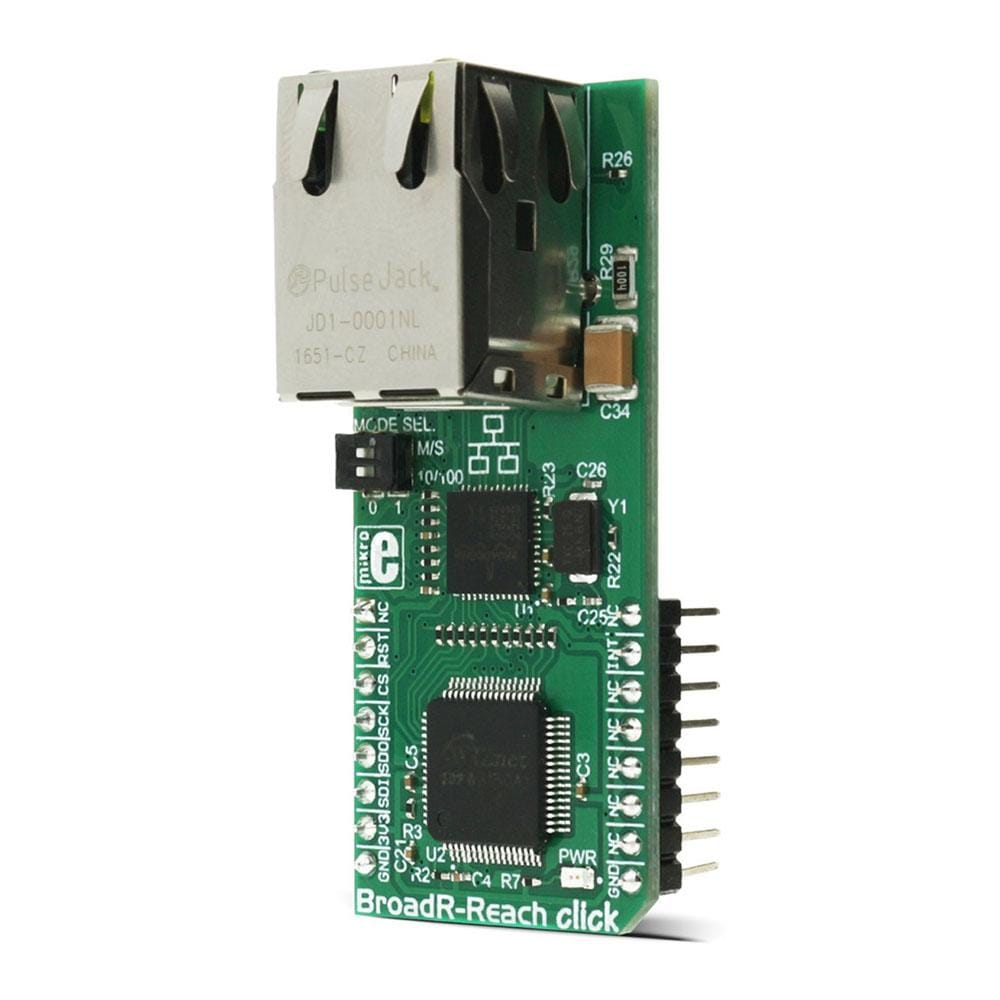
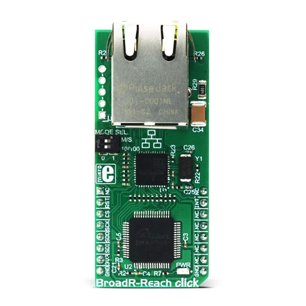
The BroadR-Reach Click Board™ brings the industry-grade communication standard to the mikroBUS, which is built to be used in an Ethernet-based open network. The Click Board™ is equipped with the BCM54811 Transceiver from Broadcom Limited, which is used to provide the hardware PHY layer for the network, and the W3150A+from WizNet, a hardware LSI protocol stack, that provides an easy and low-cost solution for high-speed Internet connectivity for digital devices by allowing simple installation of TCP/IP stack in the hardware.
Downloads
The BroadR-Reach Click Board™ brings the industry grade communication standard to the mikroBUS, which is built to be used in an Ethernet-based open network. The Click Board™ is equipped with the BCM54811 Transceiver from Broadcom Limited, which is used to provide the hardware PHY layer for the network, and the W3150A+ from WizNet, a hardware LSI protocol stack, that provides an easy and low-cost solution for high-speed Internet connectivity for digital devices by allowing simple installation of TCP/IP stack in the hardware.
BroadR-Reach point-to-point Ethernet PHY technology was eveloped by Broadcom Limited. BroadR-Reach technology is a robust Ethernet physical layer interface, designed for use in noisy environments and harsh conditions, such as in industrial networking applications. This technology allows multiple systems to simultaneously access information over the unshielded single twisted pair cable, reducing connectivity costs and cabling weight. As such, it offers a great alternative to older, rather limited standards used so far, and enables faster data rates to be transferred over the existing cable networks.
How Does The BroadR-Reach Click Board™ Work
BroadR-Reach can be used to establish full duplex Ethernet-based connectivity for applications at 100Mbps over a single, unshielded twisted pair cable. This is possible because of the used signal modulation. These attributes make this communication standard robust and immune to interference and as such, it is an ideal solution for industrial network applications or networks in any other areas with a lot of electromagnetic interferences (EMI). BroadR-Reach Click Board™ uses the physical layer IC, also known as the PHY, labelled as BCM54811 and produced by Broadcom. This IC is used for transmitting and receiving the signal on the network, on a physical level. The BCM54811 IC on Click Board™ is configured by a small, eight pin PIC16F18313 microcontroller, to work with the BroadR-Reach communication standard. This on-board microcontroller also sets the BroadR-Reach Master/Slave configuration, as well as the operating mode of 10Mbps/100 Mbps. The desired communication and operational mode can be selected by two small DIP switches on the Click Board™. For more information about the position of the switches, refer to the on-board settings and indicators table, below.
The BroadR-Reach Click Board™ has been designed to demonstrate and test 10 Mbps BroadR-Reach and 100 Mbps BroadR-Reach connectivity. However, the BCM54811 as a device is a triple-speed 10/100/1000BASE-T Gigabit Ethernet (GbE) transceiver. In addition to 10Mbps and 100Mbps BroadR-Reach connectivity, the transceiver can support 1000BASE-T, 100BASE-TX and 10BASE-T on standard Category 5 UTP cable. The 10BASE-T Ethernet can also run on standard categories 3, 4, and 5 UTP. The BCM54811 is designed to exceed IEEE specifications for noise cancellation and transmission jitter, providing consistent and reliable operation over the broadest range of existing cable infrastructures. Depending on the cable type used, it can reach up to 300m at 100Mbps or 500m at 10Mbps. The BCM54811 is fully compliant with the RGMII and MII interface specifications, allowing compatibility with industry-standard Ethernet MACs and switch controllers. The W3150A+ LSI protocol stack is used to send the data to the BCM54811 IC, which takes care of the low-level communication. The protocol stack IC itself uses the SPI interface for communication directly with the host MCU and it takes care of the proper addressing, TCP/IP stack support and other tasks needed for the network communication. It uses the standard MII (Media Independent Interface) to communicate with the Ethernet PHY chip. MikroElektronika provides libraries that help with the development of own application, by simplifying the communication between the MCU and the W3150A+ and thus, speeding up the firmware development.
SPECIFICATIONS
| Type | Ethernet |
| Applications | It can be used for realizing network in the industrial environment, and other places that require a good and reliable Ethernet-based open network. |
| On-board modules | BCM54811 BroadR-Reach capable Ethernet PHY IC from Broadcom, W3150A+ hardware LSI protocol stack by WizNet, PIC16F18313 controller from Microchip. |
| Key Features | Robust and reliable interface, designed to be used in industrial and noisy environments, only one twisted pair required for the full duplex communication. |
| Interface | GPIO,SPI |
| Compatibility | mikroBUS |
| Click board size | L (57.15 x 25.4 mm) |
| Input Voltage | 3.3V |
PINOUT DIAGRAM
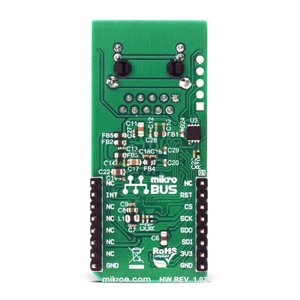
This table shows how the pinout on the BroadR-Reach Click Board™ corresponds to the pinout on the mikroBUS™ socket (the latter shown in the two middle columns).
| Notes | Pin |  |
Pin | Notes | |||
|---|---|---|---|---|---|---|---|
| NC | 1 | AN | PWM | 16 | NC | ||
| Reset | RST | 2 | RST | INT | 15 | INT | Interrupt pin |
| SPI Chip Select | CS | 3 | CS | RX | 14 | NC | |
| SPI Serial Clock | SCK | 4 | SCK | TX | 13 | NC | |
| SPI Master In Slave Out | MISO | 5 | MISO | SCL | 12 | NC | |
| SPI Master Out Slave In | MOSI | 6 | MOSI | SDA | 11 | NC | |
| Power supply | +3.3V | 7 | 3.3V | 5V | 10 | NC | |
| Ground | GND | 8 | GND | GND | 9 | GND | Ground |
ONBOARD SETTINGS AND INDICATORS
| Label | Name | Default | Description |
|---|---|---|---|
| PWR | Power LED | - | Power LED indicator. |
| SW1.1 | Mode Selection DIP Switch 1.1 | Left | Master/Slave mode selector, Master at left position, Slave at right position |
| SW1.2 | Mode Selection DIP Switch 1.2 | Left | 10/100 network selector, 10Mbps at left position, 100Mbps at right position |
| General Information | |
|---|---|
Part Number (SKU) |
MIKROE-2796
|
Manufacturer |
|
| Physical and Mechanical | |
Weight |
0.021 kg
|
| Other | |
Country of Origin |
|
HS Code Customs Tariff code
|
|
EAN |
8606018711697
|
Warranty |
|
Frequently Asked Questions
Have a Question?
Be the first to ask a question about this.

.jpg)