


Mikroelektronika d.o.o.
Tilt 2 Click Board™
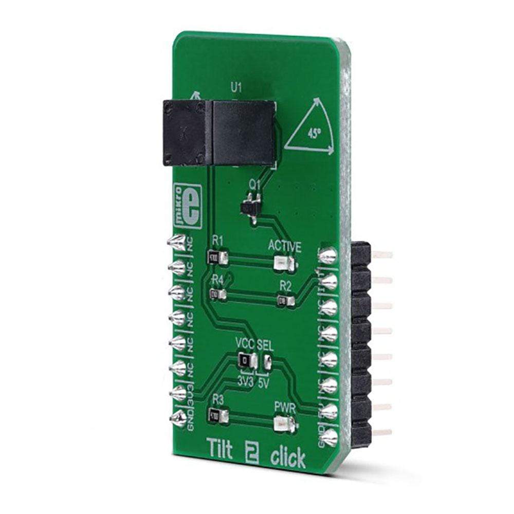
Tilt 2 Click Board™
SKU: MIKROE-3343
Couldn't load pickup availability
Overview
The Tilt 2 Click Board™ is a tilt sensor switch, which breaks the circuit when tilted to an angle of 45° or when shaken. It is a single-pole-double-throw type of switch (SPDT), which can be operated with up to 24V. The current through the switch should not exceed 25mA. The Click Board™ is equipped with the the RB-441-45, a 45° rolling ball sensor switch, which uses gold-plated terminals and a gold-plated ball, in order to minimize the contact resistance. The sensor switch is very durable, enclosed in a PBT plastic with very good electric insulation properties. It can be used in any application that relies on sensing a tilt of 45°.
The Tilt 2 Click Board™ is supported by a mikroSDK compliant library, which includes functions that simplify software development. This Click Board™ comes as a fully tested product, ready to be used on a system equipped with the mikroBUS socket.
Downloads
There are many applications that use this kind of switches. It can be used in various consumer electronic devices, such as portable heaters, video games, pinball machines, various kinds of position-activated toys, and similar applications, but it can also be used for some safety and security control systems, for soldering irons, etc.
How Does The Tilt 2 Click Board™ Work?
Conventional tilt sensors are usually made by using a drop of mercury in an enclosed casing. When tilted, the liquid mercury will close its contacts. Although efficient, this approach is not very safe, as the mercury could escape the enclosure, and if not properly sealed, there might be some mercury vapor leakage through the enclosure itself. Mercury vapors are very toxic and should be avoided.
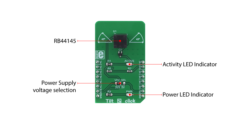
The RB-441-45, a 45° rolling ball sensor switch by C&K Switches, a factory specialized in the production of various kinds of switches. The RB-441-45 sensor does not use any mercury. It has a gold-plated ball in a PBT plastic enclosure. The PBT plastic enclosure ensures a high electrical insulation, while the gold plating ensures a low ON resistance. However, the sensor is not intended to be operated on high voltages. It should not be operated at more than 24V, while only a low signal-level current up to 25mA is allowed to flow through its contacts.
The working principle of the RB-441-45 sensor switch with the rolling ball is simple. While it stands still, perpendicular to the ground surface, a small gold-plated rolling ball will be in contact with all four gold-plated terminals. As the ball moves, it will break the contacts. This is guaranteed to happen when the enclosure is tilted by 45° (±15°). Both the ball and the contacts are gold-plated for several reasons: the ball will not stick to the contacts, the contact resistance will be minimized, and there will be no corrosion of the outer layer, ensuring the long life-cycle. The endurance of the tilt switch is specified to 100,000 cycles. The maximum voltage across the terminals should not exceed 24VDC, while the current should stay below 25mA. This prevents forming of micro-arcs that could cause surface damage and shorten the life-cycle of the sensor switch.
Besides the tilt, the RB-441-45 sensor switch is also able to detect shaking, since any displacement of the ball will break the circuit. This extends its usability to various applications where a sudden movement might occur, such when hitting or punching something. By being able to sense even this type of movements, the switch can be used in various public entertainment machines (slot, pinball, videogame consoles…).
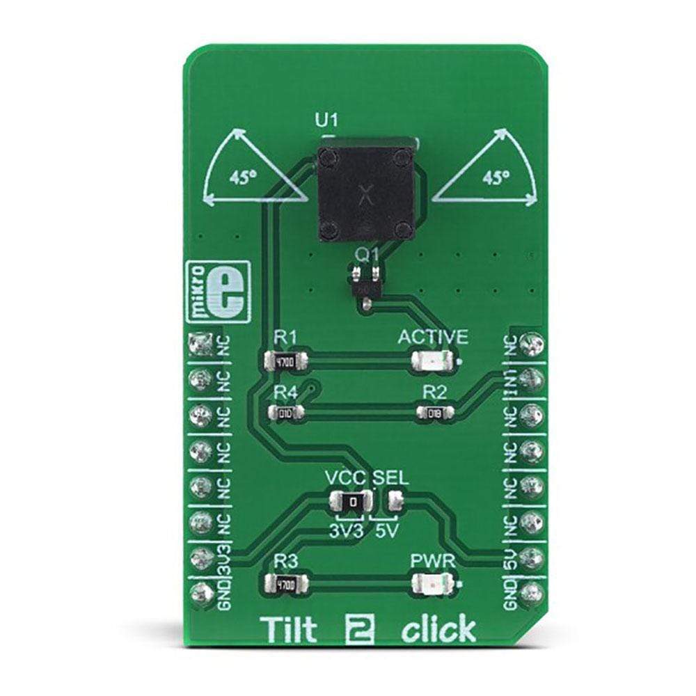
Besides the RB-441-45 sensor switch, Tilt 2 click features a LED, which is driven via the NPN transistor: when the tilt sensor switch is closed, the transistor will be in a conductive state, and LED labeled as ACTIVE will be turned ON. When the switch contacts are broken (when tilted more than 45° or while being shaken), the ACTIVE LED will be turned OFF. The VCC voltage is brought to the PIN 1. The VCC voltage can be selected by an SMD Jumper labelled as VCC SEL. It can be used to select either 3.3V or 5V from the mikroBUS™ power rails.
Besides the LED, the INT pin from the mikroBUS™ is also connected to the sensor switch, allowing the host MCU to read the state of this switch. This pin is pulled to a LOW logic level by a resistor, so when deactivated, it will not float, but pulled to a LOW Logic level instead. When Activated, this pin will be set to a HIGH logic level, determined by a VCC SEL jumper. This allows the Click board™ to be used with both 3.3V and 5V MCUs. To ensure a reliable detection and bounce-free operation, the user should utilize the debouncing routines in the software. Due to the nature of the sensor switch, the software debouncing is a better solution in this case. Unlike the hardware solution, the software debouncing allows selecting the debouncing time, according to the specific application.
Specifications
| Type | Motion,Vibration |
| Applications | The Tilt 2 Click Board™ can be used in various consumer electronic devices, such as portable heaters, video games, pinball machines, various kinds of position-activated toys, and similar applications, but it can also be used for some safety and security control systems, for soldering irons, etc. |
| On-board modules | RB-441-45, a 45° rolling ball sensor switch by C&K Switches |
| Key Features | A high durability, up to 100,000 cycles, no mercury is used, gold plated ball and contacts ensure low ON resistance. PBT plastic casing has a high dielectric constant |
| Interface | GPIO |
| Compatibility | mikroBUS |
| Click board size | M (42.9 x 25.4 mm) |
| Input Voltage | 3.3V or 5V |
Pinout diagram
This table shows how the pinout on the Tilt 2 Click Board™ corresponds to the pinout on the mikroBUS™ socket (the latter shown in the two middle columns).
| Notes | Pin | Pin | Notes | ||||
|---|---|---|---|---|---|---|---|
| NC | 1 | AN | PWM | 16 | NC | ||
| NC | 2 | RST | INT | 15 | INT | Tilt Switch Terminal | |
| NC | 3 | CS | RX | 14 | NC | ||
| NC | 4 | SCK | TX | 13 | NC | ||
| NC | 5 | MISO | SCL | 12 | NC | ||
| NC | 6 | MOSI | SDA | 11 | NC | ||
| Power Supply | 3V3 | 7 | 3.3V | 5V | 10 | 5V | Power Supply |
| Ground | GND | 8 | GND | GND | 9 | GND | Ground |
Onboard settings and indicators
| Label | Name | Default | Description |
|---|---|---|---|
| LD1 | ACTIVE | - | Activation LED indicator |
| LD2 | PWR | - | Power LED indicator |
| J1 | VCC SEL | Left | Power supply voltage selection: left position 3.3V, right position 5V |
| General Information | |
|---|---|
Part Number (SKU) |
MIKROE-3343
|
Manufacturer |
|
| Physical and Mechanical | |
Weight |
0.019 kg
|
| Other | |
EAN |
8606018714421
|
Frequently Asked Questions
Have a Question?
Be the first to ask a question about this.