Overview
The Thermo 8 Click Board™ is a very accurate digital thermometer with a very high typical measurement accuracy of ±0.25°C, and great data repeatability, with drift in the range of ±0.0625°C. Besides measuring the temperature, this Click Board™ offers a set of very useful features, such as the thermostat function, interrupt event and critical temperature alert function. The programmable thresholds allow the user to set trigger conditions, adapting the Click Board™ to any type of thermal measurement application.
The Thermo 8 Click Board™ can measure a wide range of temperatures, from -20 °C, up to +100 °C.
Downloads
Due to its high precision and flexible alerting possibilities, programmable thresholds, threshold hysteresis that prevents false alerts, and a dedicated programmable alert pin with the user selectable logic status, the Thermo 8 Click Board™ represents an ideal development solution for a variety of applications based on the accurate temperature measurement such as the PC peripherals cooling solutions, air conditioners, different types of freezers and refrigerators, battery operated portable ambient temperature thermometers, and similar.
How Does The Thermo 8 Click Board™ Work?
The Thermo 8 Click Board™ is based on the MCP9808, a digital temperature sensor with ±0.5 °C maximum accuracy, from Microchip. The MCP9808 uses a bandgap type temperature sensor, which is converted by a delta-sigma A/D converter to a digital value, available via the I2C interface. The user has the ability to select the resolution of the measurement, ranging from ±0.5°C, down to ±0.0625°C. The resolution is determined by the internal sample averaging. Therefore, a higher resolution results in longer conversion times. For example, the conversion time for the resolution of ±0.0625 °C is 250ms, while the conversion time for the resolution of ±0.5 °C is only 30ms.
The temperature is stored to an output register after the conversion is done. This register is double-buffered, which means that the new data can be written in the background, while the host microcontroller (MCU) performs a reading of the current value. The thermal data is stored as a 13-bit value, in 2's complement format. Along with the thermal data, this register also contains bits that indicate a thermal alert condition. There are three possible alert conditions. The extensive alerting engine is one of the key features of the MCP9808.
The ALERT pin of the MCP9808 is routed to the INT pin of the mikroBUS™, which is labeled as ALE on the Thermo 8 Click Board™. It can be programmed to be asserted to a HIGH or to a LOW logic level. However, the Click board™ uses the pull-up resistor to predetermine its idle state to a logic HIGH level. Depending on the application, this pin can be set to operate as a typical interrupt pin, or as a comparator. When set to operate as the interrupt, this pin will be latched until the host MCU sets the Interrupt Clear bit (bit 5 of the CONFIG register, more information in the MCP9808 datasheet).
When set to operate as the comparator, the ALERT pin will be asserted only while the alert condition exists. As soon as the temperature falls within the programmed limits, the pin will be de-asserted. While the interrupt mode is useful when an MCU is used to control some process, having to acknowledge the action, the comparator mode can be used to directly control a device, such as a cooling fan in electronic equipment, or PC peripheral.
The alert thresholds can be programmed by the user. There are dedicated registers, where the user can enter the threshold value, along with the sign. The value should be entered in 2's complement format. There is also a dedicated register where the thermal hysteresis can be entered, reducing the probability of false reporting when the temperature drifts near the threshold value. The hysteresis can be set in the range from 0 °C up to +6 °C, in four discrete steps.
Besides the threshold registers, there is another register which contains the value used to trigger a special alert mode: the critical temperature mode. This mode will force the device to work in the comparator mode, as long as the critical temperature condition exists. The same hysteresis value is applied to this threshold, reducing the probability of false reports. For more details about the alert modes, please refer to the datasheet of the MCP9808s. However, the Thermo 8 Click Board™ comes with the mikroSDK compliant library of functions, which simplify the firmware development by encapsulating all the conversion and initialization routines required by the MCP9808 IC.
The MCP9808 also supports a SHUTDOWN mode, which reduces the power consumption by turning off the sensor. However, the last conversion is still available in the output register. Even the alert pin state remains unaffected when the SHUTDOWN mode is engaged.
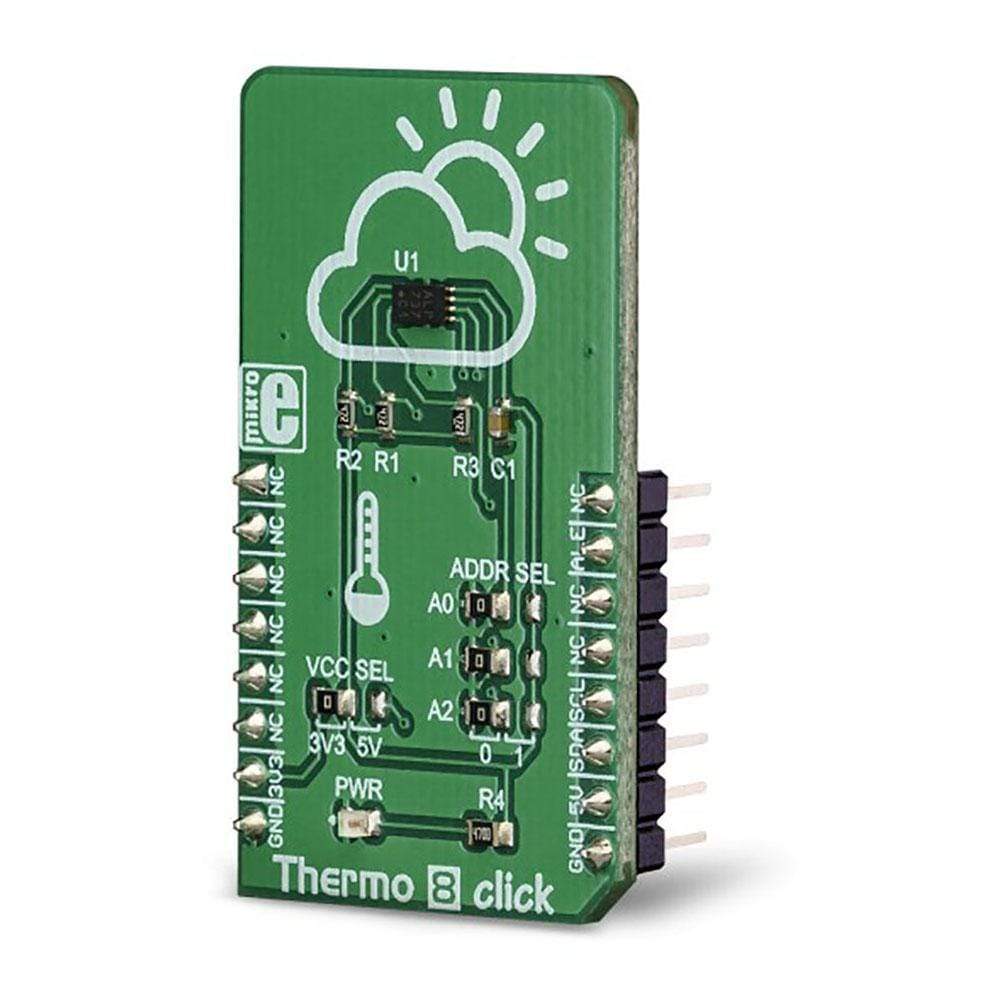
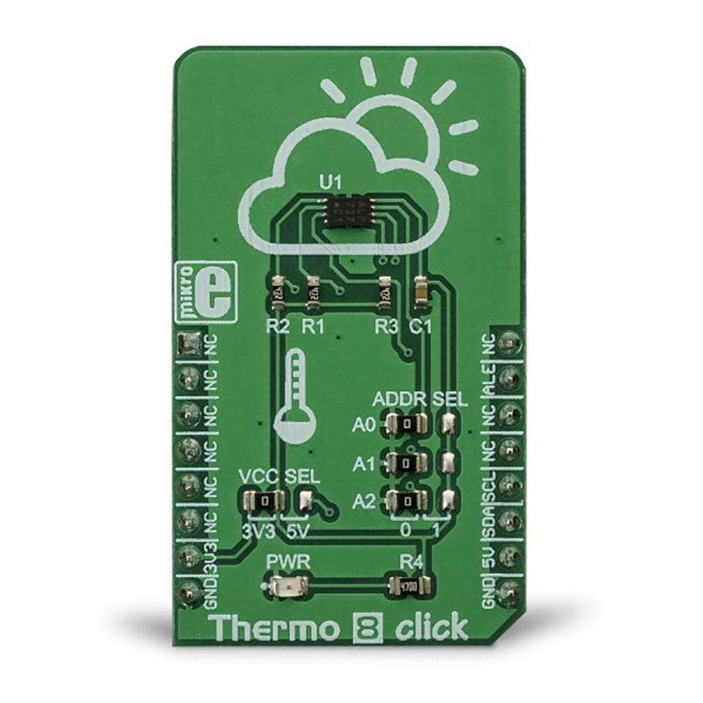
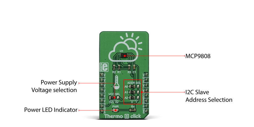
The I2C slave address of the device can be selected by switching a group of SMD jumpers, labeled as ADDR SEL. Each jumper will set the appropriate LSB of the device to either logic 0 or logic 1, determining the final I2C slave address. The power supply voltage can also be set by an SMD jumper labeled as VCC SEL, between 3.3V and 5V. This will also set the logic voltage level of the Click board™.
SPECIFICATIONS
| Type | Temperature & humidity |
| Applications | An ideal development solution for a variety of applications based on the accurate temperature measurement including PC peripheral cooling solutions, air conditioners, various types of freezers and refrigerators, battery operated portable ambient temperature thermometers, and similar |
| On-board modules | MCP9808, a digital temperature sensor with ±0.5 °C maximum accuracy, from Microchip |
| Key Features | A very high measurement accuracy and repeatability, programmable thresholds and hysteresis, a dedicated ALERT pin with a programmable function, selectable resolution, and more |
| Interface | I2C |
| Compatibility | mikroBUS |
| Click board size | M (42.9 x 25.4 mm) |
| Input Voltage | 3.3V or 5V |
PINOUT DIAGRAM
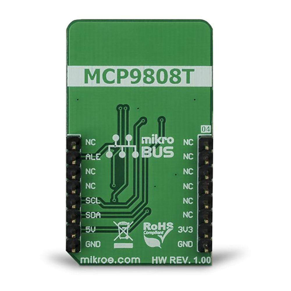
This table shows how the pinout on Thermo 8 click corresponds to the pinout on the mikroBUS™ socket (the latter shown in the two middle columns).
| Notes | Pin |  |
Pin | Notes | |||
|---|---|---|---|---|---|---|---|
| NC | 1 | AN | PWM | 16 | NC | ||
| NC | 2 | RST | INT | 15 | ALE | Alert OUT | |
| NC | 3 | CS | RX | 14 | NC | ||
| NC | 4 | SCK | TX | 13 | NC | ||
| NC | 5 | MISO | SCL | 12 | SCL | I2C Clock | |
| NC | 6 | MOSI | SDA | 11 | SDA | I2C Data | |
| Power Supply | 3V3 | 7 | 3.3V | 5V | 10 | 5V | Power Supply |
| Ground | GND | 8 | GND | GND | 9 | GND | Ground |
ONBOARD SETTINGS AND INDICATORS
| Label | Name | Default | Description |
|---|---|---|---|
| JP2 | VCC SEL | Left | Power supply voltage selection: left position 3V3, right position 5V |
| LD1 | PWR | - | Power LED indicator |
| AO-A2 | ADDR SEL | - | Network status LED indicator |
| General Information | |
|---|---|
Part Number (SKU) |
MIKROE-3290
|
Manufacturer |
|
| Physical and Mechanical | |
Weight |
0.019 kg
|
| Other | |
Country of Origin |
|
HS Code Customs Tariff code
|
|
EAN |
8606018714070
|
Warranty |
|
Frequently Asked Questions
Have a Question?
Be the first to ask a question about this.


