


Mikroelektronika d.o.o.
MUX 5 Click Board™
MUX 5 Click Board™
SKU: MIKROE-5423
Couldn't load pickup availability


Key Features
Overview
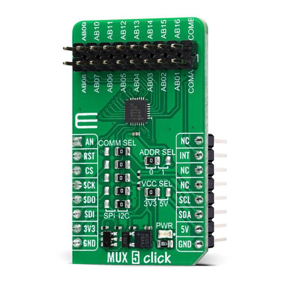
The MUX 5 Click Board™ is a compact add-on board that contains a precise multiplexing solution. This board features the MAX14661, a serially controlled, dual-channel analogue multiplexer from Analog Devices, allowing any of the 16 pins to be connected to either common pin simultaneously in any combination. The MAX14661 features Beyond-the-Rails™ capability that allows ±5.5V signals to be passed with any supply configuration alongside a configurable host interface that supports SPI and I2C serial communications. Both modes provide individual control of each independent switch so that any combination of switches can be applied. This Click board™ is designed to support various multiplexing applications like system diagnostics, data acquisition, signal switching, and many more.
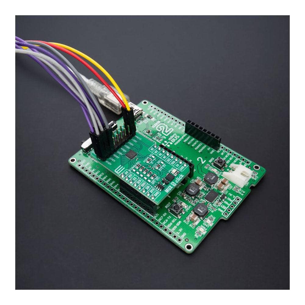
The MUX 5 Click Board™ is supported by a mikroSDK-compliant library, which includes functions that simplify software development. This Click board™ comes as a thoroughly tested product, ready to be used on a system equipped with the mikroBUS™ socket.
Downloads
How Does The MUX 5 Click Board™ Work?
The MUX 5 Click Board™ is based on the MAX14661, a serially controlled, dual-channel analog multiplexer from Analog Devices. It allows any of the 16 pins to be connected to any of the common pins, routed to the AN or INT pins of the mikroBUS™ socket, simultaneously in any combination. The MAX14661 features Beyond-the-Rails™ capability, which mainly simplifies an analog design by eliminating the need for multiple power rails and allows ±5.5V signals to be passed with any supply configuration. It integrates bias circuitry to switch high-voltage (±25V) signals while operating from a low-voltage supply with low on-resistance and fast bandwidth speeds. This Click board™ is ideal for audio and data multiplexing, interface termination, switching, industrial measurement, and instrumentation systems.
.jpg)
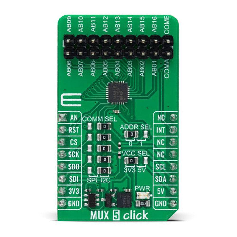
The MAX14661 allows using both I2C and SPI interfaces. Both modes provide individual control of each independent switch so that any combination of switches can be applied. The selection can be made by positioning SMD jumpers labelled as COMM SEL in an appropriate position. Note that all the jumpers' positions must be on the same side, or the Click board™ may become unresponsive. While the I2C interface is selected, the MAX14661 allows choosing the least significant bit (LSB) of its I2C slave address using the SMD jumper labelled ADDR SEL.
The MUX 5 Click Board™ also possesses an additional active-low shutdown pin, routed to the RST pin on the mikroBUS™ socket. When this pin is set to a low logic state, all registers are cleared, all switches are open, and the serial interface is not functional. All switch connections are open and tolerant of the full ±5.5V specified signal range. It is good to address that the MAX14661 consumes minimal power in this mode.
The MUX 5 Click Board™ can operate with both 3.3V and 5V logic voltage levels selected via the VCC SEL jumper. This way, it is allowed for both 3.3V and 5V capable MCUs to use the communication lines properly. However, the Click board™ comes equipped with a library containing easy-to-use functions and an example code that can be used, as a reference, for further development.
SPECIFICATIONS
| Type | DAC |
| Applications | Can be used for various multiplexing applications like system diagnostics, data acquisition, signal switching, and many more |
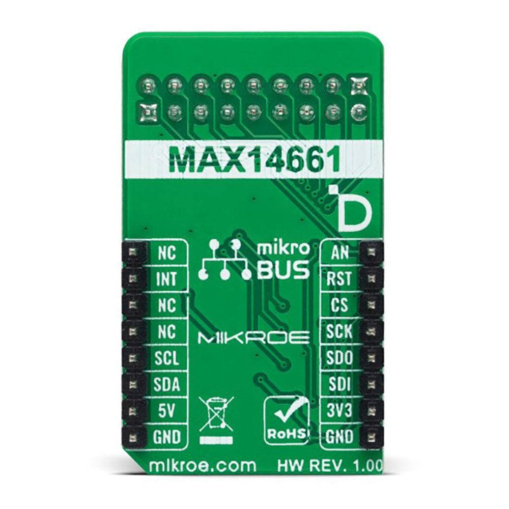
| On-board modules | MAX14661 - analog multiplexer from Analog Devices |
| Key Features | Serially controlled, dual-channel, Beyond-the-Rails capability, selectable interface, low power consumption, high performance, flexible multiplexing, programmable shadow registers allow simultaneous updating, and more |
| Interface | I2C,SPI |
| Compatibility | mikroBUS |
| Click board size | M (42.9 x 25.4 mm) |
| Input Voltage | 3.3V or 5V |
PINOUT DIAGRAM
This table shows how the pinout of the MUX 5 Click Board™ corresponds to the pinout on the mikroBUS™ socket (the latter shown in the two middle columns).
| Notes | Pin | Pin | Notes | ||||
|---|---|---|---|---|---|---|---|
| B Channel Common Signal | AN | 1 | AN | PWM | 16 | NC | |
| Shutdown | RST | 2 | RST | INT | 15 | INT | A Channel Common Signal |
| SPI Chip Select | CS | 3 | CS | RX | 14 | NC | |
| SPI Clock | SCK | 4 | SCK | TX | 13 | NC | |
| SPI Data OUT | SDO | 5 | MISO | SCL | 12 | SCL | I2C Clock |
| SPI Data IN | SDI | 6 | MOSI | SDA | 11 | SDA | I2C Data |
| Power Supply | 3.3V | 7 | 3.3V | 5V | 10 | 5V | Power Supply |
| Ground | GND | 8 | GND | GND | 9 | GND | Ground |
ONBOARD SETTINGS AND INDICATORS
| Label | Name | Default | Description |
|---|---|---|---|
| LD1 | PWR | - | Power LED Indicator |
| JP1 | VCC SEL | Left | Logic Level Voltage Selection 3V3/5V: Left position 3V3, Right position 5V |
| JP2-JP6 | COMM SEL | Right | Communication Interface Selection SPI/I2C: Left position SPI, Right position I2C |
| JP7 | ADDR SEL | Left | I2C Address Selection 0/1: Left position 0, Right position 1 |
| J1-J2 | - | Populated | MUX Channels Header |
MUX 5 CLICK ELECTRICAL SPECIFICATIONS
| Description | Min | Typ | Max | Unit |
|---|---|---|---|---|
| Supply Voltage | 3.3 | - | 5 | V |
| Analog Signal Range | -5.5 | - | 5.5 | V |
| General Information | |
|---|---|
Part Number (SKU) |
MIKROE-5423
|
Manufacturer |
|
| Physical and Mechanical | |
Weight |
0.02 kg
|
| Other | |
EAN |
8606027386343
|
Frequently Asked Questions
Have a Question?
Be the first to ask a question about this.