


Mikroelektronika d.o.o.
Analog MUX 5 Click Board™
Analog MUX 5 Click Board™
SKU: MIKROE-5120
Couldn't load pickup availability
Key Features
Overview
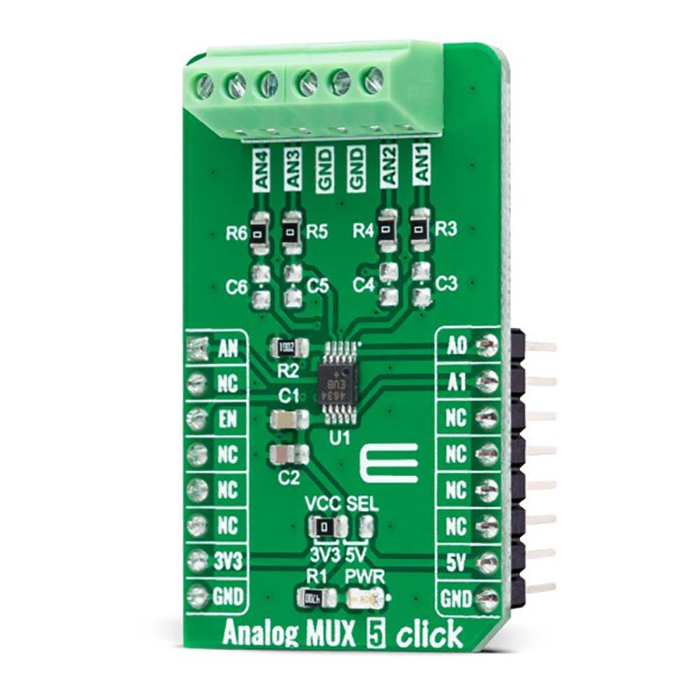
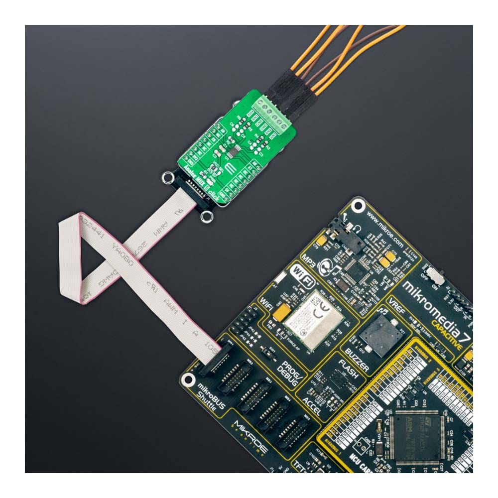
The Analog MUX 5 Click Board™ is a compact add-on board that switches one of many inputs to one output. This board features the MAX4634, a fast, low-voltage four-channel CMOS analog multiplexer from Analog Devices. This low-voltage multiplexer operates from both mikroBUS™ power rails and features 4Ω maximum ON-resistance (RON). CMOS switch construction allows the processing of analog signals within the supply voltage range. It is also characterized by an easy way of management, only through a couple of signals from the mikroBUS™ socket. This Click board™ is suitable for various applications, from industrial and instrumentation to medical, consumer, communications, and more.
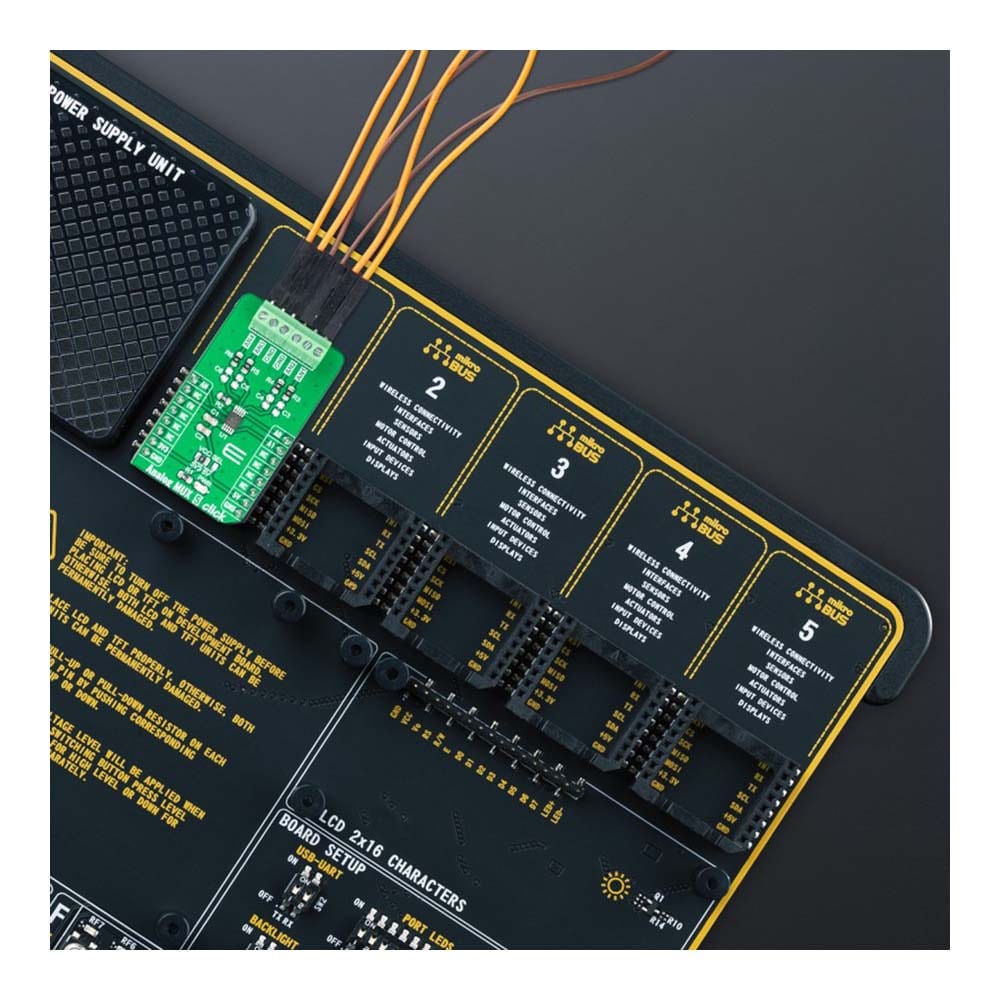
The Analog MUX 5 Click Board™ is supported by a mikroSDK compliant library, which includes functions that simplify software development. This Click board™ comes as a fully tested product, ready to be used on a system equipped with the mikroBUS™ socket.
Downloads
How Does The Analog MUX 5 Click Board™ Work?
The Analog MUX 5 Click Board™ as its foundation uses the MAX4634, a low-on-resistance, low-voltage analog multiplexer from Analog Devices. CMOS switch construction of the MAX4634 allows the processing of analog signals within its supply voltage range. It features 4Ω maximum ON-resistance (RON) and offers RON matching between switches to 0.3Ω maximum and RON flatness of 1Ω maximum ver the specified signal range. Also, all digital inputs have +0.8V and +2.4V logic thresholds, ensuring TTL/CMOS-logic compatibility with +5V operation.
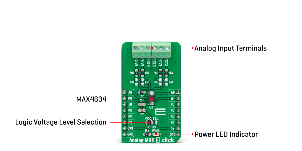
The Analog MUX 5 Click Board™ communicates with MCU using several GPIO pins. It can be enabled or disabled through the EN pin routed to the CS pin of the mikroBUS™ socket; hence, offering a switch operation to turn ON/OFF power delivery to the MAX4634. It also provides two address signals, labelled as A0 and A1 and routed to the PWM and INT pins of the mikroBUS™ socket, that determine the activation of the desired analog input channel based on their setup while monitoring of that input analog signal is done using AN pin of the mikroBUS™ socket.
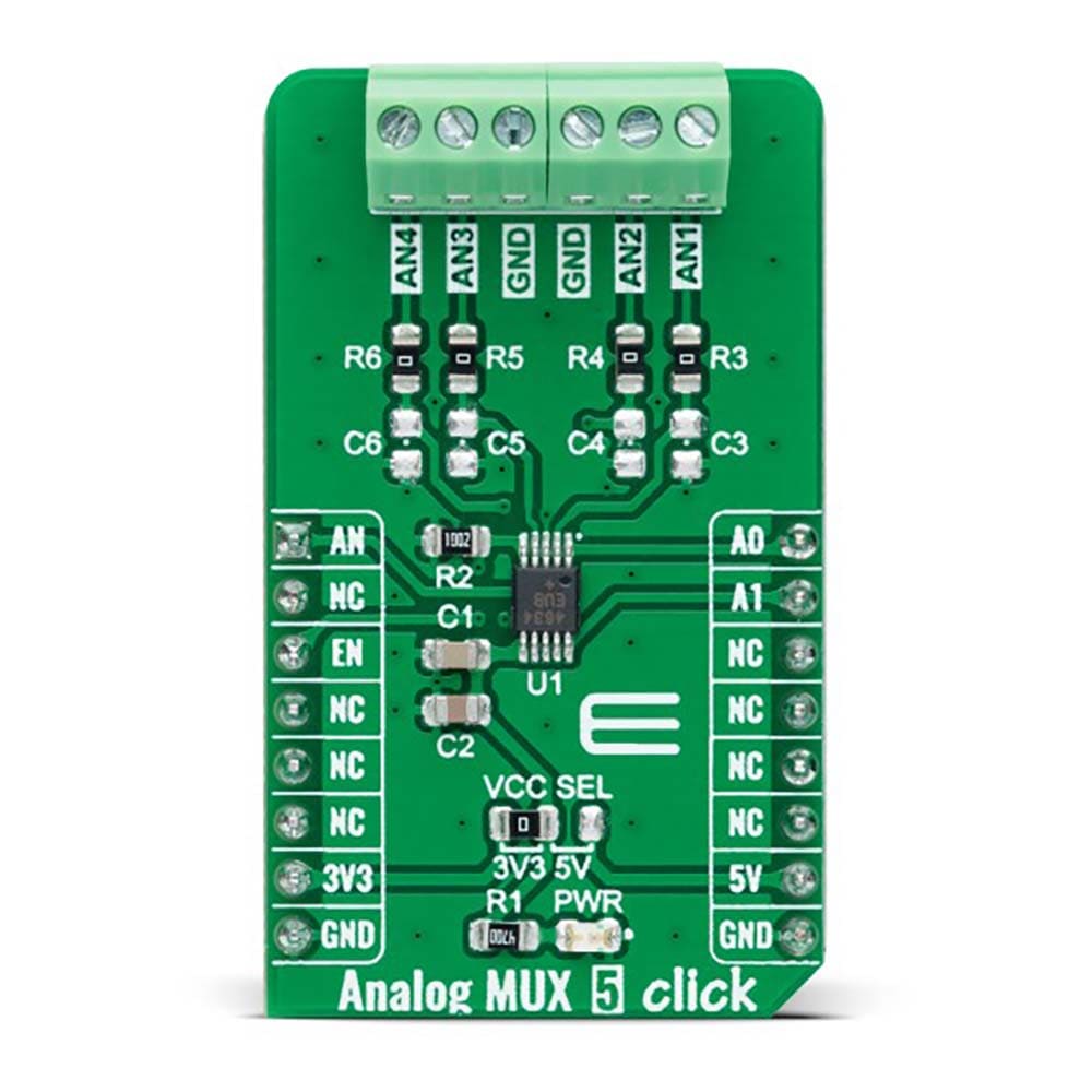
Each analog input has a jumper for its hardware activation or deactivation from R3 to R6 and capacitors for additional filtering of the input channels from C3 to C6. Proper power-supply sequencing is recommended for all CMOS devices. Before applying analog signals or logic inputs, always apply the power supply first, especially if the analog or logic signals are not current-limited.
The Analog MUX 5 Click Board™ can operate with both 3.3V and 5V logic voltage levels selected via the VCC SEL jumper. This way, it is allowed for both 3.3V and 5V capable MCUs to use the communication lines properly. However, the Click board™ comes equipped with a library that contains easy-to-use functions and an example code that can be used, as a reference, for further development.
SPECIFICATIONS
| Type | Measurements |
| Applications | The Analog MUX 5 Click Board™ can be used for various applications, from industrial and instrumentation to medical, consumer, communications, and more |
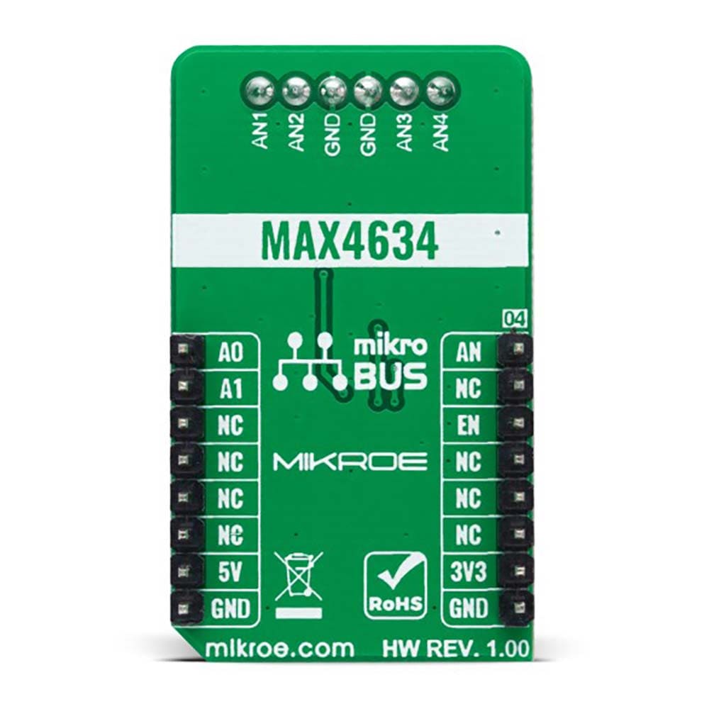
| On-board modules | MAX4634 - low-on-resistance, low-voltage analog multiplexer from Analog Devices |
| Key Features | Low power consumption, fast, CMOS switch construction, guaranteed RON, VCC range signal handling, TTL/CMOS-logic compatible, pin-controllable, and more |
| Interface | Analog,GPIO |
| Compatibility | mikroBUS |
| Click board size | M (42.9 x 25.4 mm) |
| Input Voltage | 3.3V or 5V |
PINOUT DIAGRAM
This table shows how the pinout of the Analog MUX 5 Click Board™ corresponds to the pinout on the mikroBUS™ socket (the latter shown in the two middle columns).
| Notes | Pin | Pin | Notes | ||||
|---|---|---|---|---|---|---|---|
| Analog Signal | AN | 1 | AN | PWM | 16 | A0 | Address Control 0 |
| NC | 2 | RST | INT | 15 | A1 | Address Control 1 | |
| Enable | EN | 3 | CS | RX | 14 | NC | |
| NC | 4 | SCK | TX | 13 | NC | ||
| NC | 5 | MISO | SCL | 12 | NC | ||
| NC | 6 | MOSI | SDA | 11 | NC | ||
| Power Supply | 3.3V | 7 | 3.3V | 5V | 10 | NC | |
| Ground | GND | 8 | GND | GND | 9 | GND | Ground |
ONBOARD SETTINGS AND INDICATORS
| Label | Name | Default | Description |
|---|---|---|---|
| LD1 | PWR | - | Power LED Indicator |
| JP1 | VCC SEL | Left | Logic Level Voltage Selection 3V3/5V: Left position 3V3, Right position 5V |
ANALOG MUX CLICK ELECTRICAL SPECIFICATIONS
| Description | Min | Typ | Max | Unit |
|---|---|---|---|---|
| Supply Voltage | 3.3 | - | 5 | V |
| Analog Input Range | 0 | - | 5 | V |
| ON-Resistance | - | - | 4 | Ω |
| Operating Temperature Range | -40 | 25 | +85 | °C |
| General Information | |
|---|---|
Part Number (SKU) |
MIKROE-5120
|
Manufacturer |
|
| Physical and Mechanical | |
Weight |
0.02 kg
|
| Other | |
EAN |
8606027388675
|
Frequently Asked Questions
Have a Question?
Be the first to ask a question about this.