


Mikroelektronika d.o.o.
H-Bridge 10 Click Board™
H-Bridge 10 Click Board™
SKU: MIKROE-5108
Couldn't load pickup availability


Overview
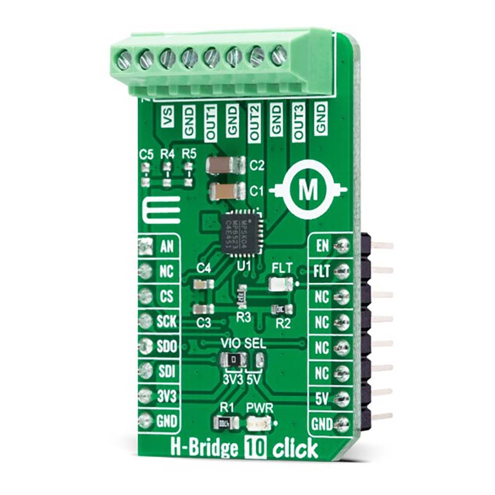
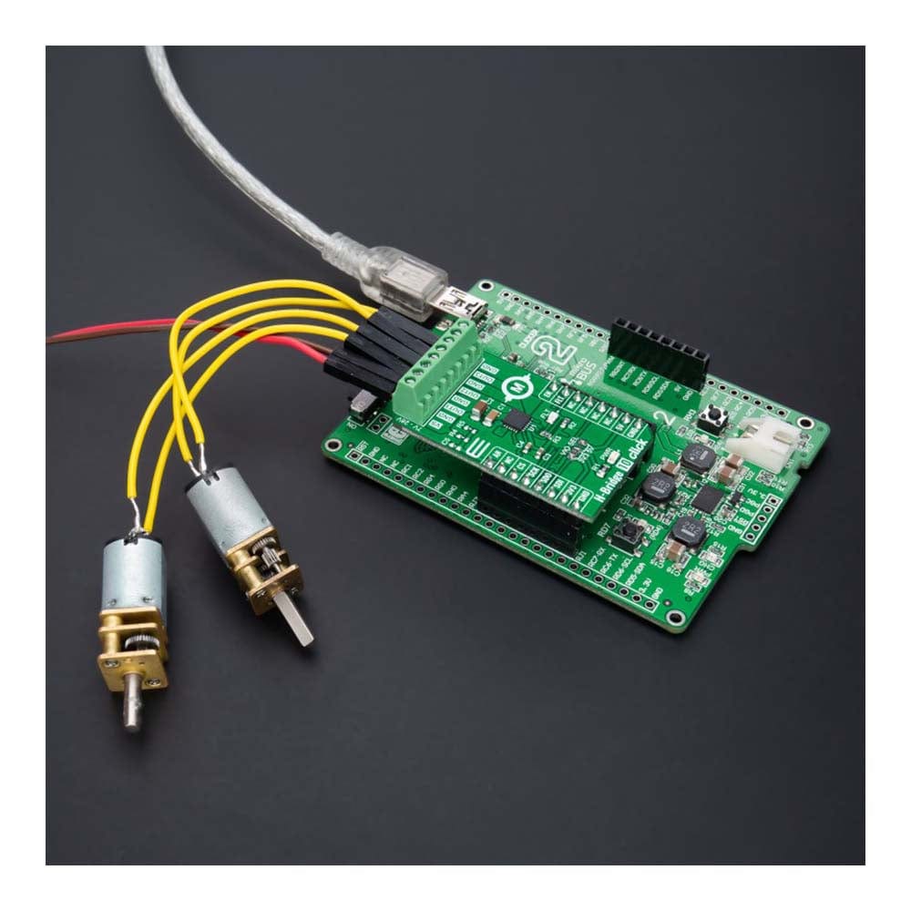
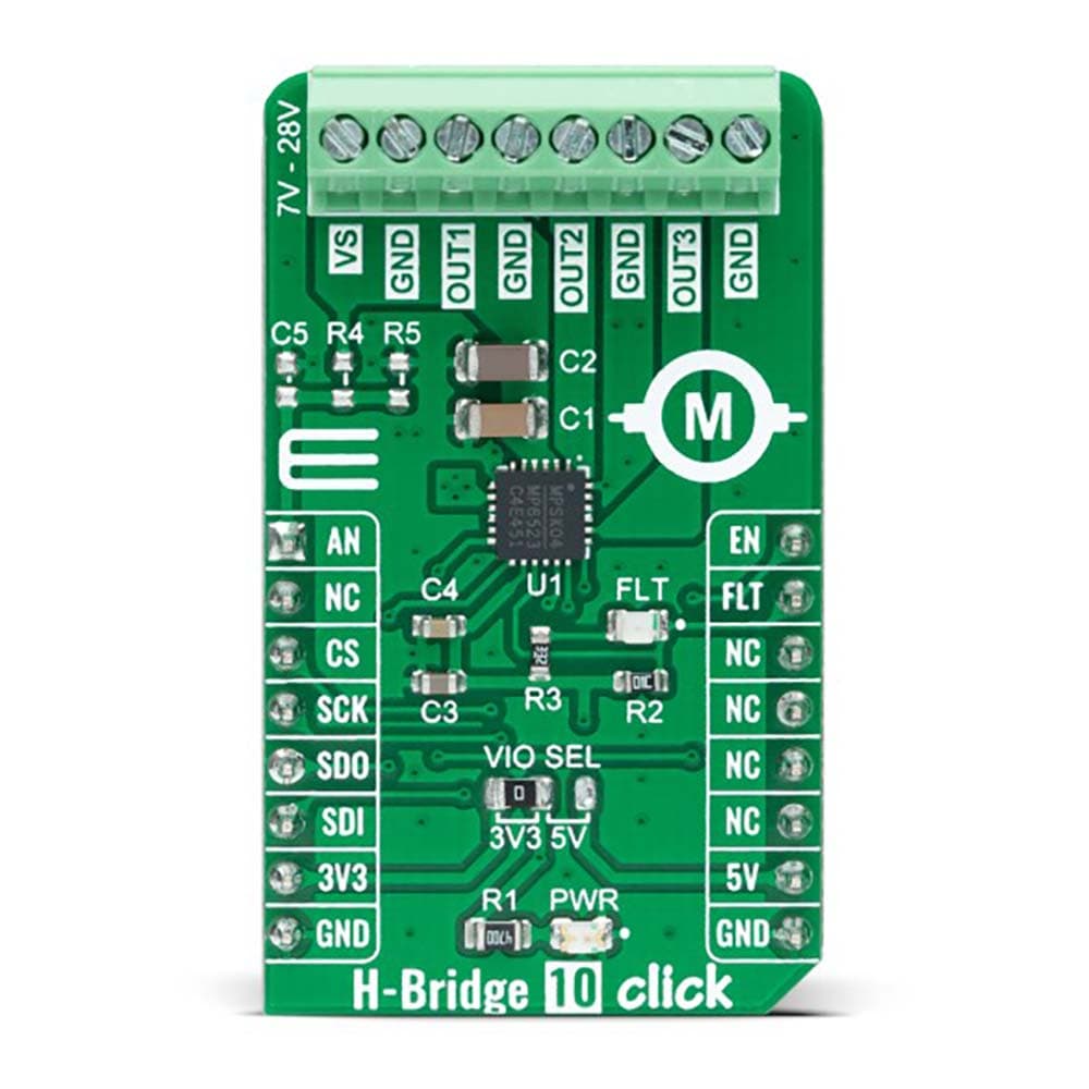
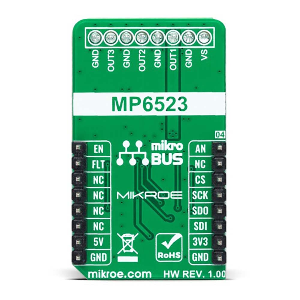
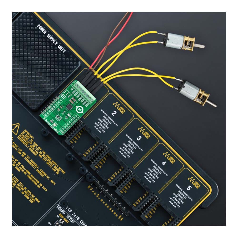
The H-Bridge 10 Click Board™ is a compact add-on board containing H-bridge outputs that let you control a DC motor to go backward or forward. This board features the MP6523, a triple, half-bridge, DMOS, output driver with integrated power MOSFETs that can drive up to three different loads from Monolithic Power Systems (MPS). The MP6523 is rated for an operating voltage range from 7V to 28V. It is SPI-configurable and has various diagnostic functions. Complete protection features include short-circuit protection (SCP), under-voltage protection (UVP), and thermal shutdown, alongside an onboard power supply existence-check circuit. This Click board™ is suitable as a multiple brushed DC motor driver for driving various loads in automotive and industrial applications, and more.
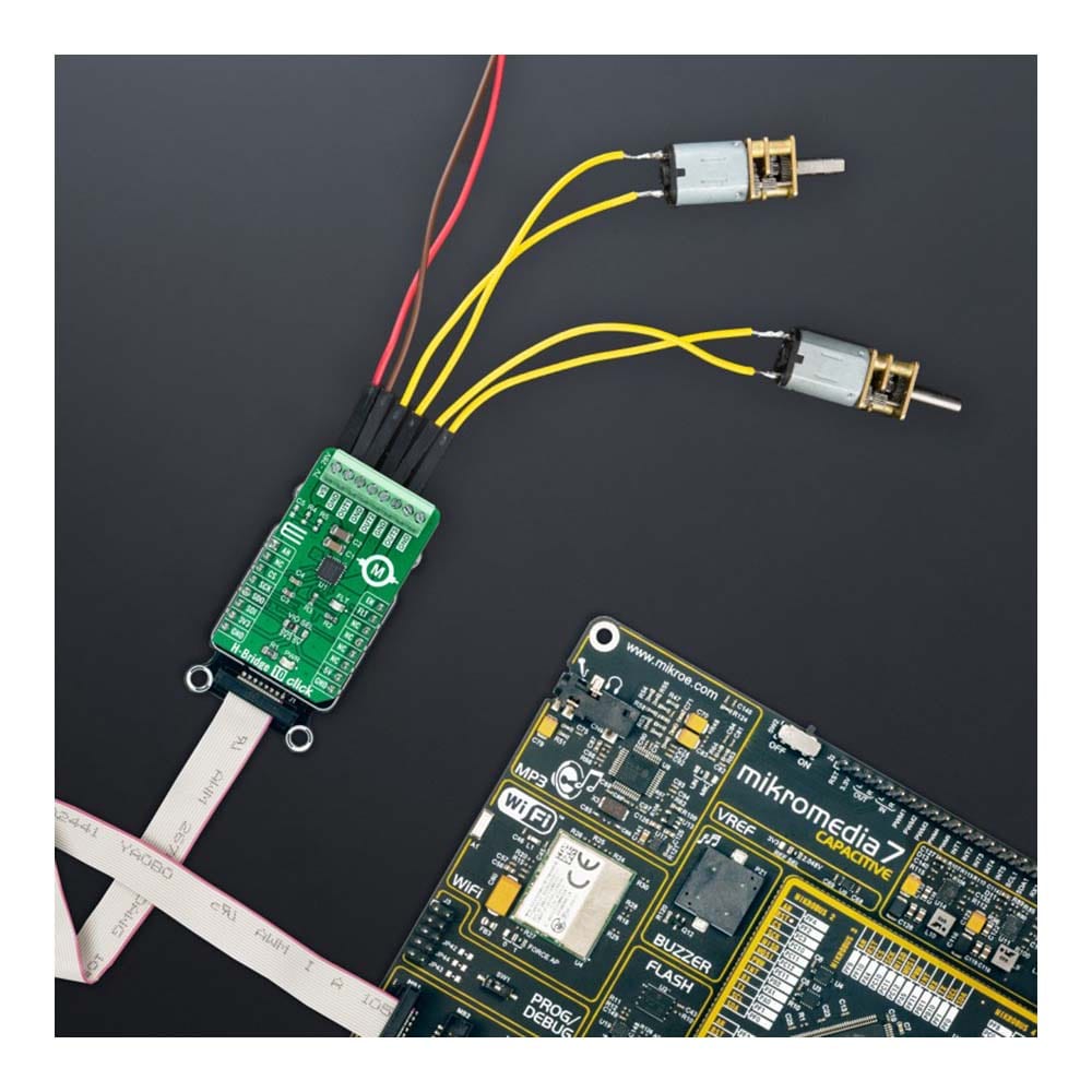
The H-Bridge 10 Click Board™ is supported by a mikroSDK compliant library, which includes functions that simplify software development. This Click board™ comes as a fully tested product, ready to be used on a system equipped with the mikroBUS™ socket.
Downloads
How Does The H-Bridge 10 Click Board™ Work?
The H-Bridge 10 Click Board™ as its foundation uses the MP6523, a triple, half-bridge motor driver from Monolithic Power Systems (MPS). The MP6523 contains three MOSFET half-bridge outputs that can drive up to three different loads with separate controls for high-side or low-side MOSFETs from a standard serial data interface. It has a low quiescent current in standby mode, making it suitable for many applications. The input voltage ranges from 7V to 28V, with up to 0.9A output current capability per channel. Complete protection features include short-circuit protection, under-voltage protection, and thermal shutdown.
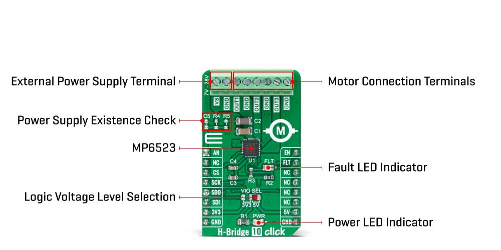
The H-Bridge 10 Click Board™ communicates with MCU through a standard SPI interface and operates at clock rates up to 3MHz, providing data in digital format of 16-bits. It also can be enabled or disabled through the EN pin routed to the PWM pin of the mikroBUS™ socket; hence, offering a switch operation to turn ON/OFF power delivery to the MP6523. It also provides a fault status indication signal, labelled as FLT and routed to the INT pin of the mikroBUS™ socket, alongside its red LED indicator marked as FLT to indicate different fault conditions such as current limit and thermal shutdown.
A unique addition that this board has is checking the existence of an external power supply. By adding resistors R4 and R5, the user can monitor and check the presence of an external power supply on the VS terminal via the voltage divider routed to the AN pin of the mikroBUS™ socket.
The H-Bridge 10 Click Board™ can operate with both 3.3V and 5V logic voltage levels selected via the VCC SEL jumper. This way, it is allowed for both 3.3V and 5V capable MCUs to use the communication lines properly. However, the Click board™ comes equipped with a library that contains easy-to-use functions and an example code that can be used, as a reference, for further development.
SPECIFICATIONS
| Type | Brushed |
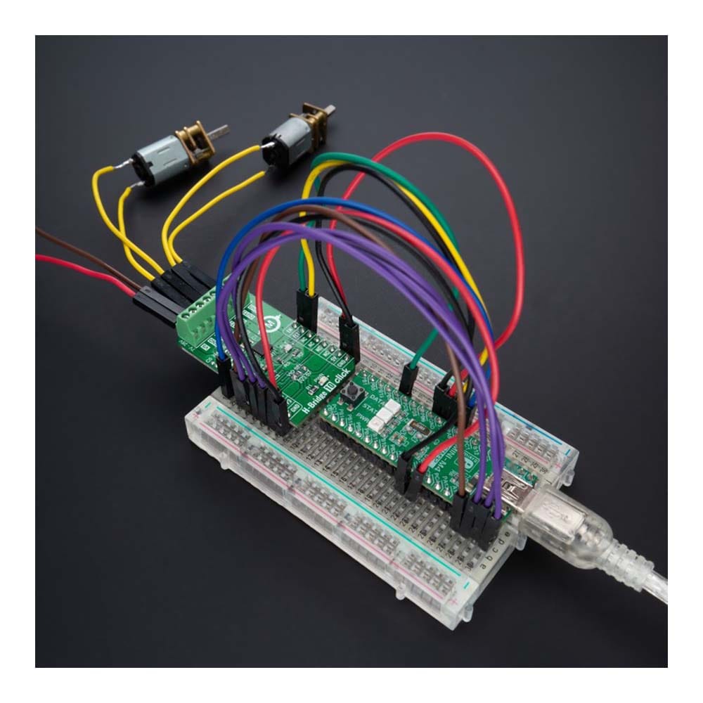
| Applications | The H-Bridge 10 Click Board™ can be used as a multiple brushed DC motor driver for driving various loads in automotive and industrial applications, and more |
| On-board modules | MP6523 - triple, half-bridge motor driver from Monolithic Power Systems (MPS) |
| Key Features | Integrated power MOSFETs drive up to three different loads, low power consumption, high level of programming, high level diagnostics, protection features, and more |
| Interface | Analog,SPI |
| Compatibility | mikroBUS |
| Click board size | M (42.9 x 25.4 mm) |
| Input Voltage | 3.3V or 5V,External |
PINOUT DIAGRAM
This table shows how the pinout of the H-Bridge 10 Click Board™ corresponds to the pinout on the mikroBUS™ socket (the latter shown in the two middle columns).
| Notes | Pin | Pin | Notes | ||||
|---|---|---|---|---|---|---|---|
| Power Supply Check | AN | 1 | AN | PWM | 16 | EN | Enable |
| NC | 2 | RST | INT | 15 | FLT | Fault Indication | |
| SPI Chip Select | CS | 3 | CS | RX | 14 | NC | |
| SPI Clock | SCK | 4 | SCK | TX | 13 | NC | |
| SPI Data OUT | SDO | 5 | MISO | SCL | 12 | NC | |
| SPI Data IN | SDI | 6 | MOSI | SDA | 11 | NC | |
| Power Supply | 3.3V | 7 | 3.3V | 5V | 10 | 5V | Power Supply |
| Ground | GND | 8 | GND | GND | 9 | GND | Ground |
ONBOARD SETTINGS AND INDICATORS
| Label | Name | Default | Description |
|---|---|---|---|
| LD1 | PWR | - | Power LED Indicator |
| LD2 | FLT | - | Fault LED Indicator |
| JP1 | VCC SEL | Left | Logic Level Voltage Selection 3V3/5V: Left position 3V3, Right position 5V |
| R4-R5 | R4-R5 | Unpopulated | Power Supply Existence Check Jumpers |
H-BRIDGE 10 CLICK ELECTRICAL SPECIFICATIONS
| Description | Min | Typ | Max | Unit |
|---|---|---|---|---|
| Supply Voltage VCC | 3.3 | - | 5 | V |
| External Supply Voltage VS | 7 | - | 28 | V |
| Maximum Output Current (per channel) | - | - | 0.9 | A |
| Operating Temperature Range | -40 | +25 | +120 | °C |
| General Information | |
|---|---|
Part Number (SKU) |
MIKROE-5108
|
Manufacturer |
|
| Physical and Mechanical | |
Weight |
0.02 kg
|
| Other | |
EAN |
8606027389061
|
Frequently Asked Questions
Have a Question?
Be the first to ask a question about this.