


Mikroelektronika d.o.o.
LED Driver 14 Click Board™
LED Driver 14 Click Board™
SKU: MIKROE-4996
Couldn't load pickup availability

Key Features
Overview
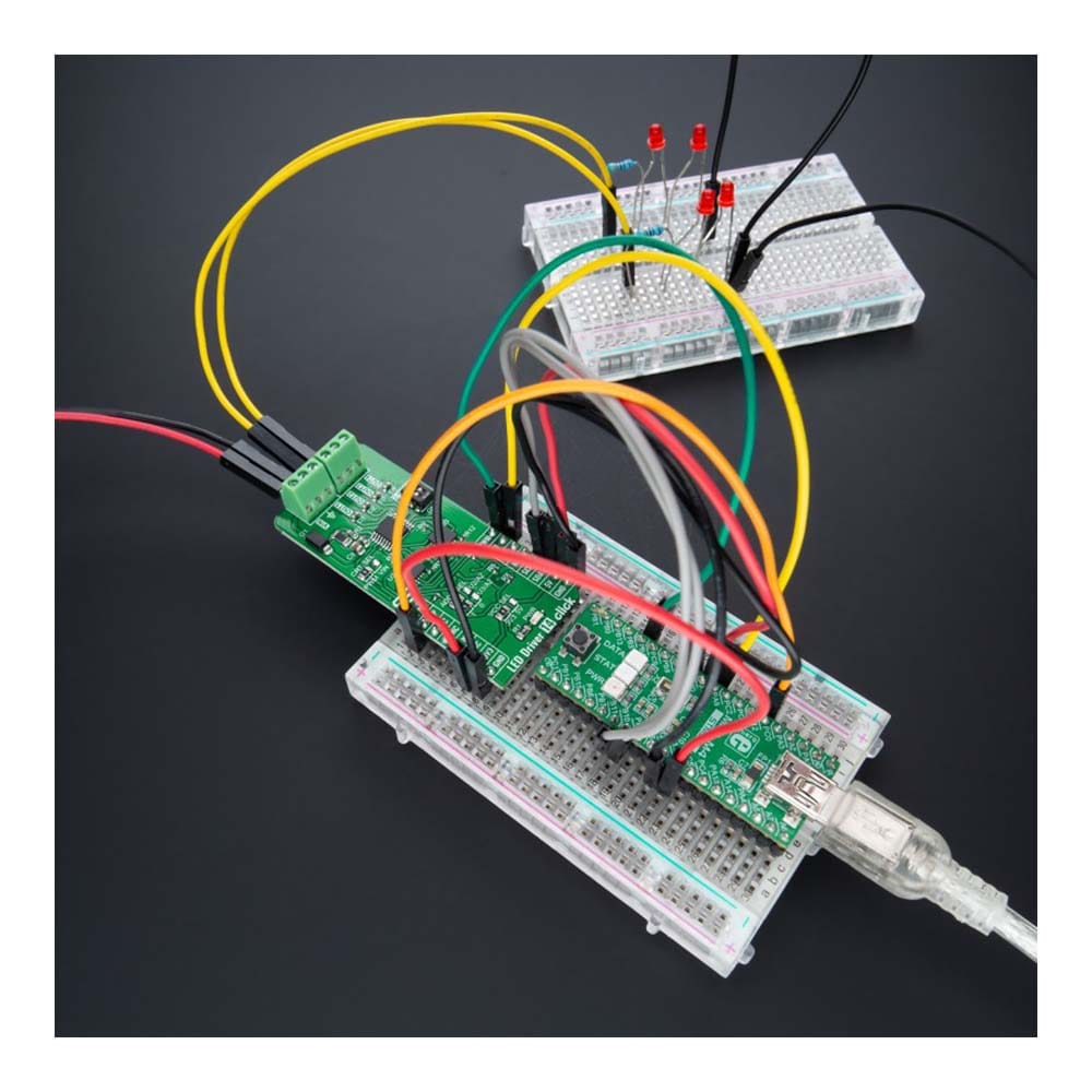
The LED Driver 14 Click Board™ is a compact add-on board that simplifies the control of multiple LEDs. This board features the BD18337EFV-M, a reliable four-channel constant current LED driver from Rohm Semiconductor. It is powered by an external power supply in the range of 5.5V to 20V, providing a maximum output current of 150mA per channel. The BD18337EFV-M also comes with the possibility for up to 3 LEDs in series on its output OUTx pin and built-in energy sharing control, selectable operational mode, and multiple built-in protection functions that protect the circuit during abnormalities. This Click board™ is ideal for LED rear lamps (turn/stop), fog lamps, and turn signals for automotive applications.
The LED Driver 14 Click Board™ is supported by a mikroSDK compliant library, which includes functions that simplify software development. This Click board™ comes as a fully tested product, ready to be used on a system equipped with the mikroBUS™ socket.
Downloads
How Does The LED Driver 14 Click Board™ Work?
The LED Driver 14 Click Board™ is based on the BD18337EFV-M, a four-channel constant current LED driver with built-in MOSFET ideal for LED rear lamps (turn/stop), fog lamps, and turn signals for automotive use from Rohm Semiconductor. The BD18337EFV-M incorporates a proprietary thermal dissipation circuit and individual LED control function to drive LED lamps with different specifications by one driver, allowing the possibility for up to 3 LEDs in series on its output OUTx pin. It also has integrated protection circuitry to guard against output-short, overvoltage, LED short-circuit protections, and overtemperature.
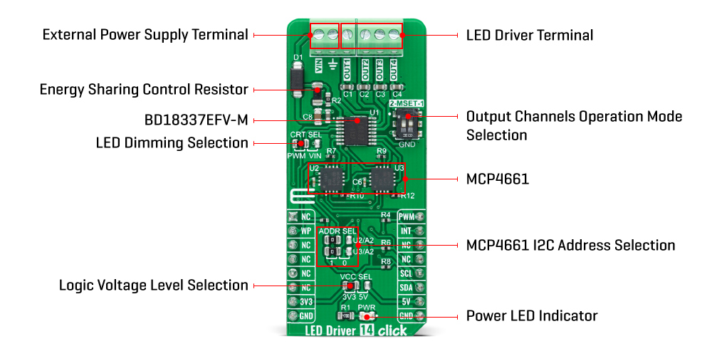
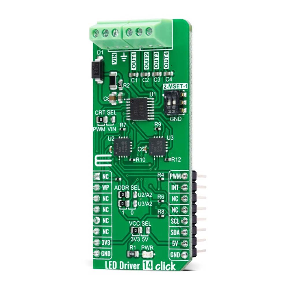
The LED Driver 14 Click Board™ provides an output current of 150mA per channel with an output current accuracy of ±5%, limited by two MCP4661 digital potentiometers from Microchip Technology, which establishes communication with the MCU via I2C serial interface. The MCP4661 also allows the choice of the least significant bit (LSB) of its I2C slave address by positioning SMD jumpers labelled as ADDR SEL to an appropriate position marked as 1 and 0. The MCP4661 also has a configurable Write Protection function labelled as WP routed on the RST pin of the mikroBUS™ socket, which protects the entire memory and all registers from write operations and must be set to a low logic state to inhibit all the write operations.
The BD18337EFV-M offers two ways to implement LED dimming: analog dimming and PWM dimming. Both methods control the average current flowing through the LEDs. The analog dimming can be achieved by adjusting the LED current by using an external voltage source on the VIN terminal, while the PWM dimming is implemented by direct control of the dimming control signal routed to the PWM pin on the mikroBUS™ socket. The selection can be made by positioning the SMD jumper labelled as CRT SEL to an appropriate position marked as PWM or VIN.
This board also has a two-channel switch labelled as MSET, which allows changing output channel operation mode based on detecting an LED error. It also uses the INT pin of the mikroBUS™ socket in two ways, used as a 'fault' indicator which immediately notifies the host when a fault condition occurs or as an input that disables the output current. The output channel operation mode is automatically selected according to a switch position. More information about these selectable modes can be found in the attached datasheet.
The LED Driver 14 Click Board™ supports an external power supply for the motor, which can be connected to the input terminal labelled as VIN and should be within the range of 5.5V to 20V (typically about 12V). This wide range can lead to significant device power consumption in applications where a high input voltage is applied to the device, and the output is relatively low. This amount of power can increase the BD18337EFV-M internal temperature to an unacceptable level depending on the package's thermal resistance. The BD18337EFV-M employs an Energy Sharing Control to solve this issue, which dissipates the extra power that can overheat the device in external resistors R2 and R3 (R3 is unpopulated by default configuration).
The LED Driver 14 Click Board™ can operate with both 3.3V and 5V logic voltage levels selected via the VCC SEL jumper. This way, it is allowed for both 3.3V and 5V capable MCUs to use the communication lines properly. However, the Click board™ comes equipped with a library containing easy-to-use functions and an example code that can be used, as a reference, for further development.
SPECIFICATIONS
| Type | LED Drivers |
| Applications | The LED Driver 14 Click Board™ can be used for LED rear lamps (turn/stop), fog lamps, and turn signals for automotive applications |
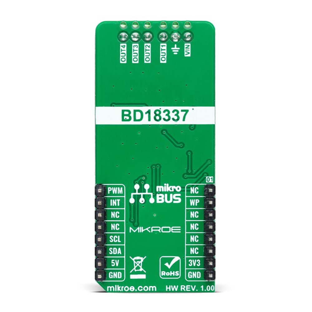
| On-board modules | BD18337EFV-M - four-channel constant current LED driver from Rohm Semiconductor |
| Key Features | Built-in energy sharing control, high reliability, PWM or analog dimming control, license lamp mode, protection features, and more |
| Interface | I2C,PWM |
| Compatibility | mikroBUS |
| Click board size | L (57.15 x 25.4 mm) |
| Input Voltage | 3.3V or 5V,External |
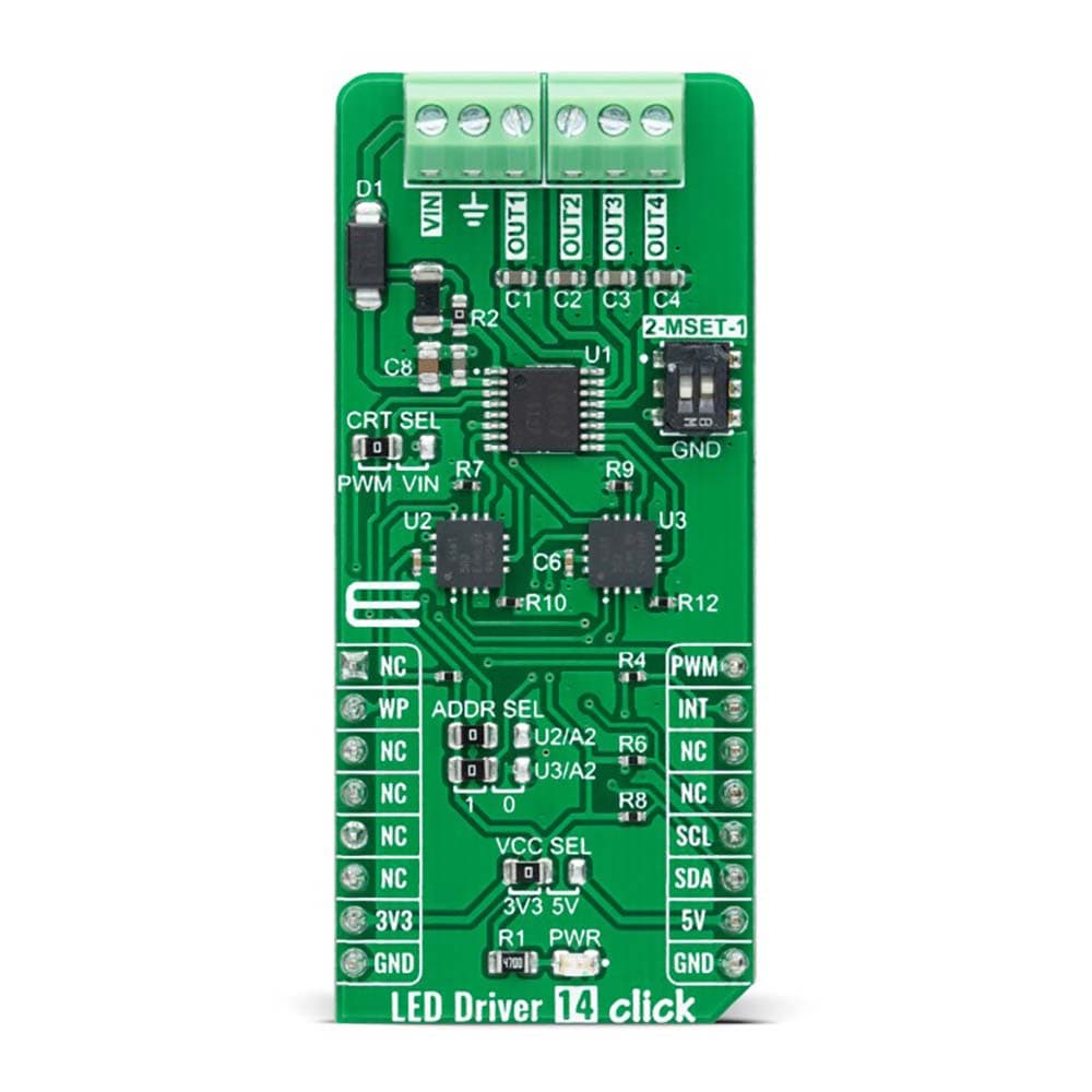
PINOUT DIAGRAM
This table shows how the pinout of the LED Driver 14 Click Board™ corresponds to the pinout on the mikroBUS™ socket (the latter shown in the two middle columns).
| Notes | Pin | Pin | Notes | ||||
|---|---|---|---|---|---|---|---|
| NC | 1 | AN | PWM | 16 | PWM | PWM Signal | |
| Digipot Write Protect | WP | 2 | RST | INT | 15 | INT | Interrupt |
| NC | 3 | CS | RX | 14 | NC | ||
| NC | 4 | SCK | TX | 13 | NC | ||
| NC | 5 | MISO | SCL | 12 | SCL | I2C Clock | |
| NC | 6 | MOSI | SDA | 11 | SDA | I2C Data | |
| Power Supply | 3.3V | 7 | 3.3V | 5V | 10 | 5V | Power Supply |
| Ground | GND | 8 | GND | GND | 9 | GND | Ground |
ONBOARD SETTINGS AND INDICATORS
| Label | Name | Default | Description |
|---|---|---|---|
| LD1 | PWR | - | Power LED Indicator |
| JP1 | VCC SEL | Left | Logic Level Voltage Selection 3V3/5V: Left position 3V3, Right position 5V |
| JP2 | CRT SEL | Left | LED Dimming Selection PWM/VIN: Left position PWM, Right position VIN |
| JP3-JP4 | ADDR SEL | Left | I2C Address Selection 1/0: Left position 1, Right position 0 |
| SW1 | MSET | Down | Output Channels Operation Mode Switch |
LED DRIVER 14 CLICK ELECTRICAL SPECIFICATIONS
| Description | Min | Typ | Max | Unit |
|---|---|---|---|---|
| Supply Voltage VCC | 3.3 | - | 5 | V |
| External Supply Voltage VIN | 5.5 | - | 20 | V |
| Maximum Output Current | - | - | 150 | mA |
| Output Current Accuracy | - | 5 | - | % |
| Operating Temperature Range | -40 | +25 | +120 | °C |
| General Information | |
|---|---|
Part Number (SKU) |
MIKROE-4996
|
Manufacturer |
|
| Physical and Mechanical | |
Weight |
0.02 kg
|
| Other | |
EAN |
8606027389276
|
Frequently Asked Questions
Have a Question?
Be the first to ask a question about this.