


Mikroelektronika d.o.o.
Clock Gen 6 Click Board™
Clock Gen 6 Click Board™
SKU: MIKROE-4973
Couldn't load pickup availability
Key Features
Overview
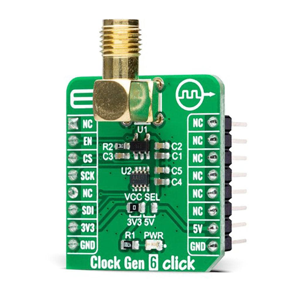
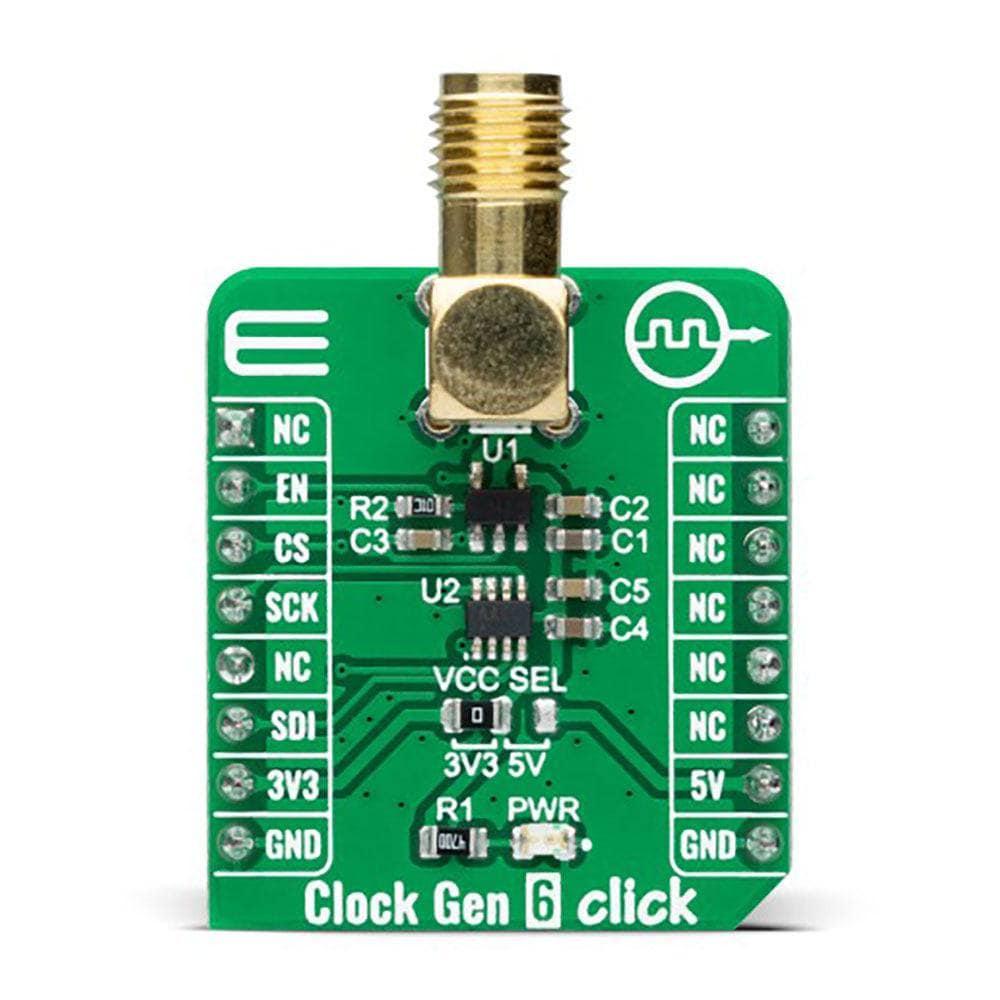
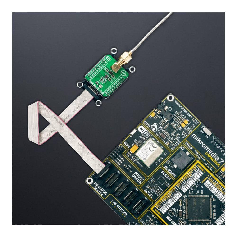
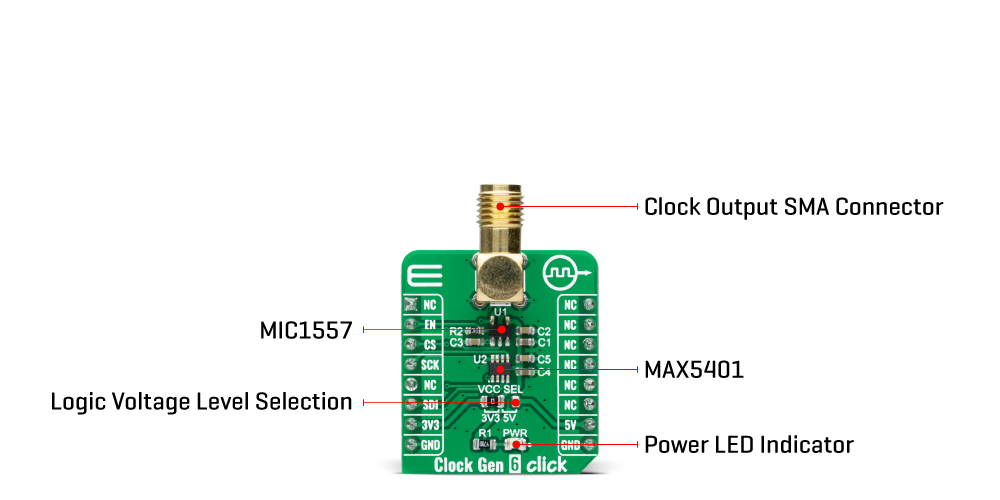
The Clock Gen 6 Click Board™ is a compact add-on board representing a digital oscillator solution. This board features the MIC1557, an IttyBitty CMOS RC oscillator designed to provide rail-to-rail pulses for precise time delay or frequency generation from Microchip Technology. The MIC1557 has a single threshold and trigger connection, internally connected, for astable (oscillator) operation only. It also has an enable/reset control signal routed to the RST pin of the mikroBUS™ socket, which controls the bias supply to the oscillator’s internal circuitry and optimizes power consumption used for oscillator power ON/OFF purposes. In addition, it provides the ability to select the desired frequency programmed via a digital potentiometer, the MAX5401. This Click board™ is suitable for pulse generation, precision timer, time-delay generation, and similar applications.
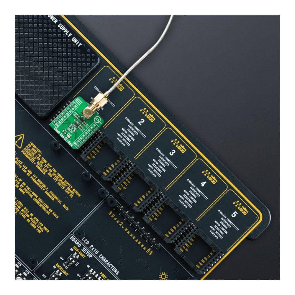
The Clock Gen 6 Click Board™ is supported by a mikroSDK compliant library, which includes functions that simplify software development. This Click board™ comes as a fully tested product, ready to be used on a system equipped with the mikroBUS™ socket.
Downloads
How Does The Clock Gen 6 Click Board™ Work?
The Clock Gen 6 Click Board™ as its foundation uses the MIC1557, a low-power digital frequency solution providing the logic for creating a simple RC oscillator circuit from Microchip Technology. The MIC1557 offers rail-to-rail pulses for precise frequency generation alongside a single threshold and trigger connection, internally connected, for astable (oscillator) operation only with programmable output frequency and enable/reset control signal intended as an oscillator with a Shutdown capability.
As mentioned before, the astable oscillator switches between two states, ON and OFF, producing a continuous square wave. The MIC1557 is optimized for this function by tying the two comparator inputs together, the threshold and trigger pins (THR and TRG), forming a T/T pin. The external capacitor charges slowly through the external resistor presented in the form of a digital potentiometer by which the user can pass through the frequency range and thus adjust the desired output.
By replacing the resistor with a digital potentiometer, the user can easily program frequency output as performed on this Click board™. For this purpose, the digital potentiometer MAX5401, which communicates with the MCU via 3-Wire SPI serial interface, is used to set the resistance on the MIC1557 OUT line, adjusting the frequency up to 5MHz.
Alongside SPI communication, this Click board™ also uses one additional pin. The Enable pin, labelled as EN and routed to the RST pin of the mikroBUS™ socket, optimizes power consumption and is used for power ON/OFF purposes (controls the bias supply to the oscillator's internal circuitry). When the MIC1557 is deselected, the supply current is less than 1μA, and the device is placed in a Shutdown state. Forcing the EN pin low resets the device by setting the flip flop, causing the output to a low logic state.
ThClock Gen 6 Click Board™ can operate with both 3.3V and 5V logic voltage levels selected via the VCC SEL jumper. This way, it is allowed for both 3.3V and 5V capable MCUs to use the communication lines properly. However, the Click board™ comes equipped with a library containing easy-to-use functions and an example code that can be used, as a reference, for further development.
SPECIFICATIONS
| Type | Clock generator |
| Applications | Can be used for applications such as pulse generation, precision timer, time-delay generation, and more |
| On-board modules | MIC1557 - RC oscillator from Microchip Technology |
| Key Features | Low power consumption, high precision, astable oscillator operation, programmable output, enable/reset feature, and more |
| Interface | GPIO,SPI |
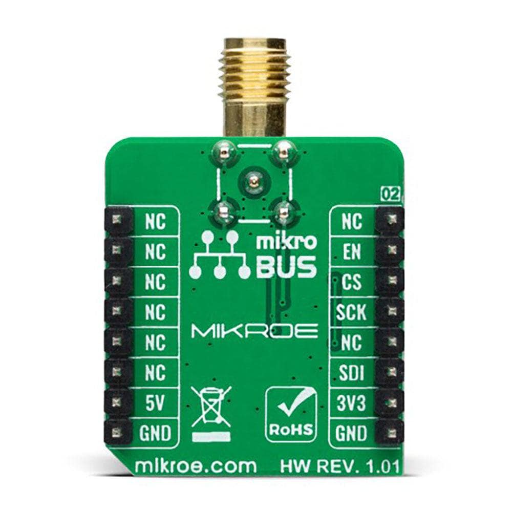
| Compatibility | mikroBUS |
| Click board size | S (28.6 x 25.4 mm) |
| Input Voltage | 3.3V or 5V |
PINOUT DIAGRAM
This table shows how the pinout on Clock Gen 6 Click corresponds to the pinout on the mikroBUS™ socket (the latter shown in the two middle columns).
| Notes | Pin | Pin | Notes | ||||
|---|---|---|---|---|---|---|---|
| NC | 1 | AN | PWM | 16 | NC | ||
| Enable | EN | 2 | RST | INT | 15 | NC | |
| SPI Chip Select | CS | 3 | CS | RX | 14 | NC | |
| SPI Clock | SCK | 4 | SCK | TX | 13 | NC | |
| SPI Data OUT | SDO | 5 | MISO | SCL | 12 | NC | |
| SPI Data IN | SDI | 6 | MOSI | SDA | 11 | NC | |
| Power Supply | 3.3V | 7 | 3.3V | 5V | 10 | 5V | Power Supply |
| Ground | GND | 8 | GND | GND | 9 | GND | Ground |
ONBOARD SETTINGS AND INDICATORS
| Label | Name | Default | Description |
|---|---|---|---|
| LD1 | PWR | - | Power LED Indicator |
| JP1 | VCC SEL | Left | Logic Level Voltage Selection 3V3/5V: Left position 3V3, Right position 5V |
CLOCK GEN 6 CLICK ELECTRICAL SPECIFICATIONS
| Description | Min | Typ | Max | Unit |
|---|---|---|---|---|
| Supply Voltage | 3.3 | - | 5 | V |
| Frequency Range | - | - | 5 | MHz |
| Operating Temperature Range | -40 | +25 | +85 | °C |
| General Information | |
|---|---|
Part Number (SKU) |
MIKROE-4973
|
Manufacturer |
|
| Physical and Mechanical | |
Weight |
0.02 kg
|
| Other | |
EAN |
8606027388132
|
Frequently Asked Questions
Have a Question?
Be the first to ask a question about this.