


Mikroelektronika d.o.o.
LED Driver 13 Click Board™
LED Driver 13 Click Board™
SKU: MIKROE-4965
Couldn't load pickup availability
Key Features
Overview
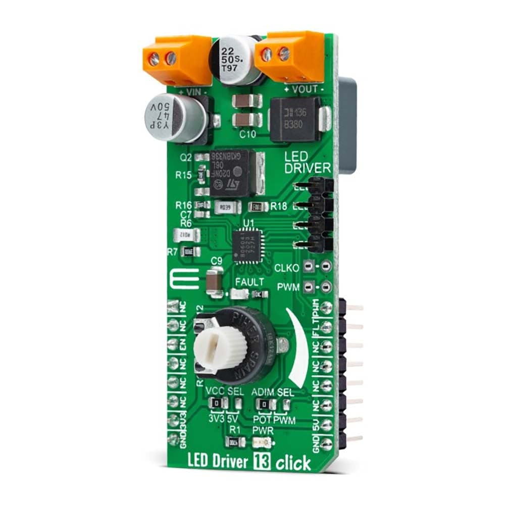
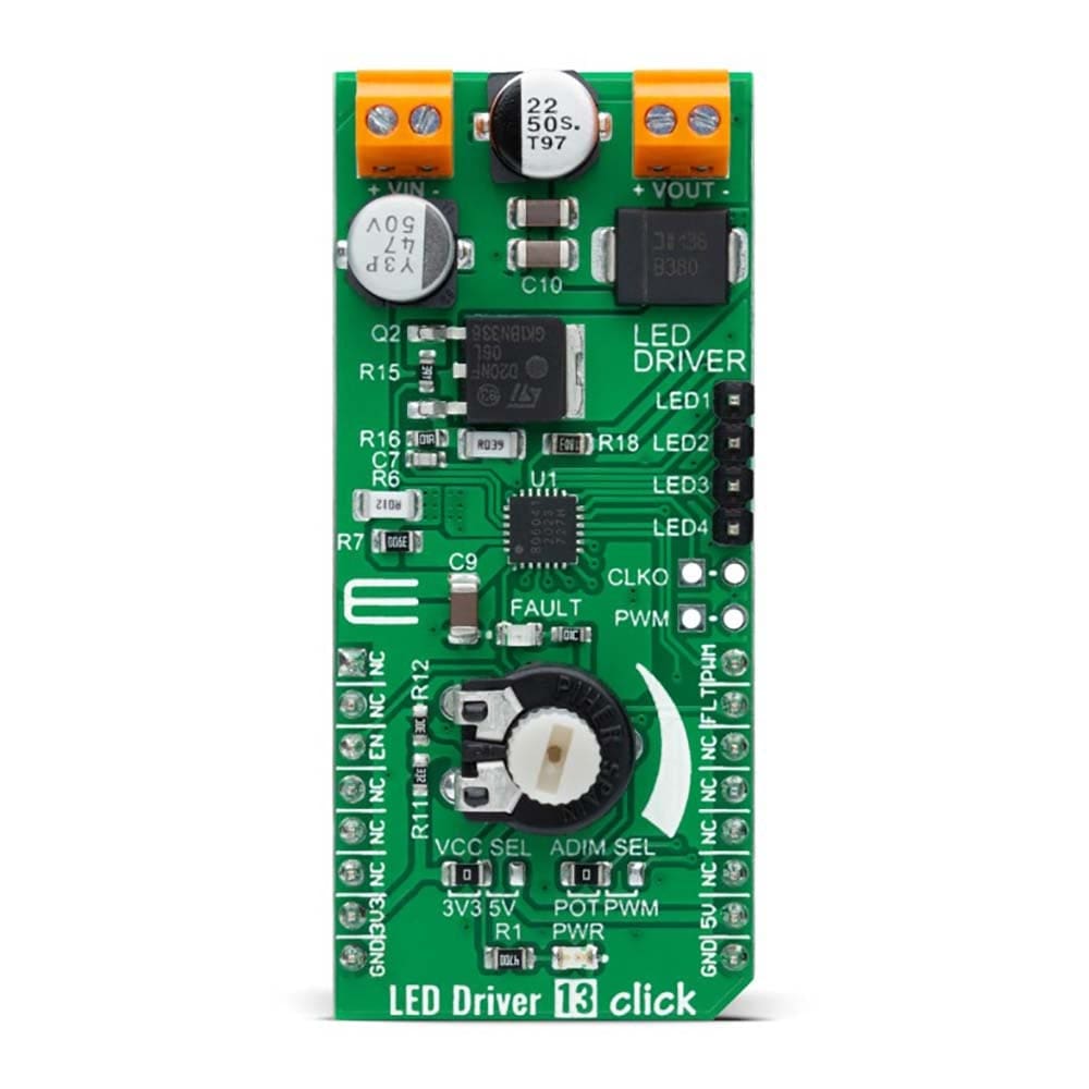
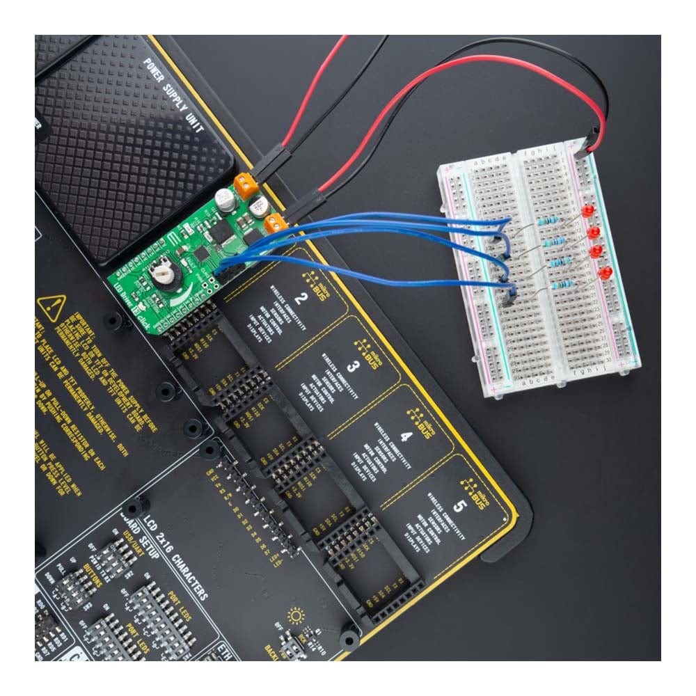
The LED Driver 13 Click Board™ is a compact add-on board that simplifies the control of multiple LEDs. This board features the A80604-1, a 4-channel LED driver designed at a switching frequency of 400kHz that provides 150mA per channel from Allegro Microsystems. It is powered by an external power supply in the range of 6V to 18V, providing an output voltage of approximately 26V, which is used to power LEDs connected to LED channels. On the logical side, this board uses both 3V3 and 5V with mikroBUS™ power rails and communicates with the MCU via GPIO pins. In addition, the user is given the option of analog or digital LED dimming selection, using a PWM pin from the mikroBUS™ socket or via an onboard potentiometer/external PWM signal. This Click board™ is suitable for various automotive applications, such as infotainment backlighting, interior/exterior lighting, heads-up display, and more.
The LED Driver 13 Click Board™ is supported by a mikroSDK compliant library, which includes functions that simplify software development. This Click board™ comes as a fully tested product, ready to be used on a system equipped with the mikroBUS™ socket.
Downloads
How Does The Work?
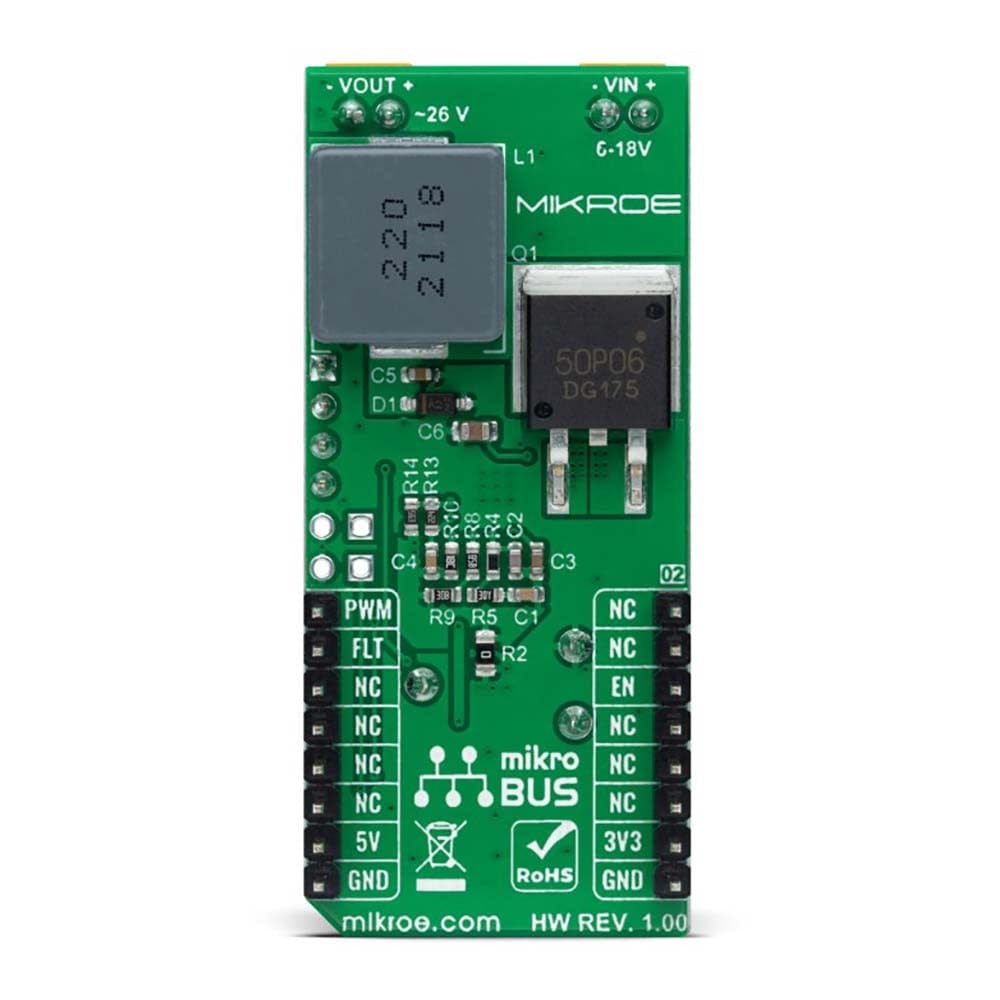
The LED Driver 13 Click Board™ as its foundation uses the A80604-1, a multi-output LED driver for automotive applications designed at a switching frequency of 400kHz from Allegro Microsystems. The A80604-1 implements a current-mode boost/SEPIC converter with gate driver for onboard external N-channel MOSFET. Thus, it provides an output current of 150mA per channel at an output voltage of approximately 26V, limited by the input voltage of the A80604-1, which must be in the range of 6V to 18V for proper operation. It also has integrated protection circuitry to guard against output short, overvoltage, LED short-circuit protections, and overtemperature.
The LED Driver 13 Click Board™ offers two ways to implement the LED dimming: analog dimming via an onboard potentiometer or through an external PWM signal applied on the onboard header labelled as PWM, and PWM dimming using a PWM pin from the mikroBUS™ socket. Using the patented Pre-Emptive Boost control, an LED brightness contrast ratio of 15,000:1 can be achieved using PWM dimming at 200Hz. A higher ratio of 150,000:1 is possible when using a combination of PWM and analog dimming. The analog dimming selection can be made by positioning the SMD jumper labelled as ADIM SEL to an appropriate position marked as POT or PWM.
The switching frequency of the A80604-1 can be externally synchronized to an external clock or generated internally - programmed between 260kHz and 2.3MHz. The spread-spectrum technique (with user-programmable dithering range and modulation frequency) is provided to reduce EMI. A clock-out signal, available on the onboard header labelled CLKO, allows other converters to be synchronized to the switching frequency of A80604-1.
As mentioned in the product description, the LED Driver 13 Click Board™ communicates with MCU using several GPIO pins. The Enable pin, labelled as EN and routed to the CS pin of the mikroBUS™ socket, optimizes power consumption used for power ON/OFF purposes of the board. In addition, it also uses a fault pin labelled as FLT and routed to the INT pin of the mikroBUS™ socket, which indicates the previously mentioned fault conditions to an external system if any fault occurs during operation. This fault signal is also visually indicated via a red LED labelled FAULT. Once the fault is removed, the soft-start process will continue.
The LED Driver 13 Click Board™ can operate with both 3.3V and 5V logic voltage levels selected via the VCC SEL jumper. This way, it is allowed for both 3.3V and 5V capable MCUs to use the communication lines properly. However, the Click board™ comes equipped with a library containing easy-to-use functions and an example code that can be used, as a reference, for further development.
SPECIFICATIONS
| Type | LED Drivers |
| Applications | The LED Driver 13 Click Board™ be used for various automotive applications, such as infotainment backlighting, interior/exterior lighting, heads-up display, and more |
| On-board modules | A80604-1 - multi-output LED driver for automotive applications from Allegro Microsystems |
| Key Features | Designed at a switching frequency of 400kHz, operate in Boost or SEPIC mode for flexible output , provides 150mA per channel, programmable boost frequency, selectable LED Dimming feature, onboard protection circuitry, and more |
| Interface | GPIO,PWM |
| Compatibility | mikroBUS |
| Click board size | L (57.15 x 25.4 mm) |
| Input Voltage | 3.3V or 5V,External |
PINOUT DIAGRAM
This table shows how the pinout for the LED Driver 13 Click Board™ corresponds to the pinout on the mikroBUS™ socket (the latter shown in the two middle columns).
| Notes | Pin | Pin | Notes | ||||
|---|---|---|---|---|---|---|---|
| NC | 1 | AN | PWM | 16 | PWM | PWM Signal | |
| NC | 2 | RST | INT | 15 | FLT | Fault Indicator | |
| Enable | EN | 3 | CS | RX | 14 | NC | |
| NC | 4 | SCK | TX | 13 | NC | ||
| NC | 5 | MISO | SCL | 12 | NC | ||
| NC | 6 | MOSI | SDA | 11 | NC | ||
| Power Supply | 3.3V | 7 | 3.3V | 5V | 10 | 5V | Power Supply |
| Ground | GND | 8 | GND | GND | 9 | GND | Ground |
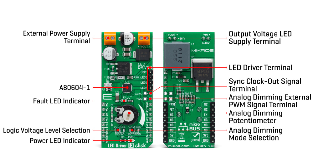
ONBOARD SETTINGS AND INDICATORS
| Label | Name | Default | Description |
|---|---|---|---|
| LD1 | PWR | - | Power LED Indicator |
| LD2 | FAULT | - | Fault LED Indicator |
| JP1 | VCC SEL | Left | Logic Level Voltage Selection 3V3/5V: Left position 3V3, Right position 5V |
| JP2 | ADIM SEL | Left | Analog Dimming Mode Selection POT/PWM: Left position POT, Right position PWM |
| J1 | PWR | Unpopulated | Analog Dimming External PWM Signal Header |
| J2 | CLKO | Unpopulated | Sync Clock-Out Signal Header |
| J3 | LED DRIVER | Populated | LED Driver Header |
LED DRIVER 13 CLICK ELECTRICAL SPECIFICATIONS
| Description | Min | Typ | Max | Unit |
|---|---|---|---|---|
| Supply Voltage VCC | 3.3 | - | 5 | V |
| External Supply Voltage VIN | 6 | - | 18 | V |
| Output LED Supply Voltage VOUT | - | 26 | - | V |
| LED Channel Current | - | 150 | - | mA |
| Operating Temperature Range | -40 | +25 | +120 | °C |
| General Information | |
|---|---|
Part Number (SKU) |
MIKROE-4965
|
Manufacturer |
|
| Physical and Mechanical | |
Weight |
0.02 kg
|
| Other | |
EAN |
8606027389627
|
Frequently Asked Questions
Have a Question?
Be the first to ask a question about this.