


Mikroelektronika d.o.o.
RF Meter 3 Click Board™
RF Meter 3 Click Board™
SKU: MIKROE-4906
Couldn't load pickup availability


Overview
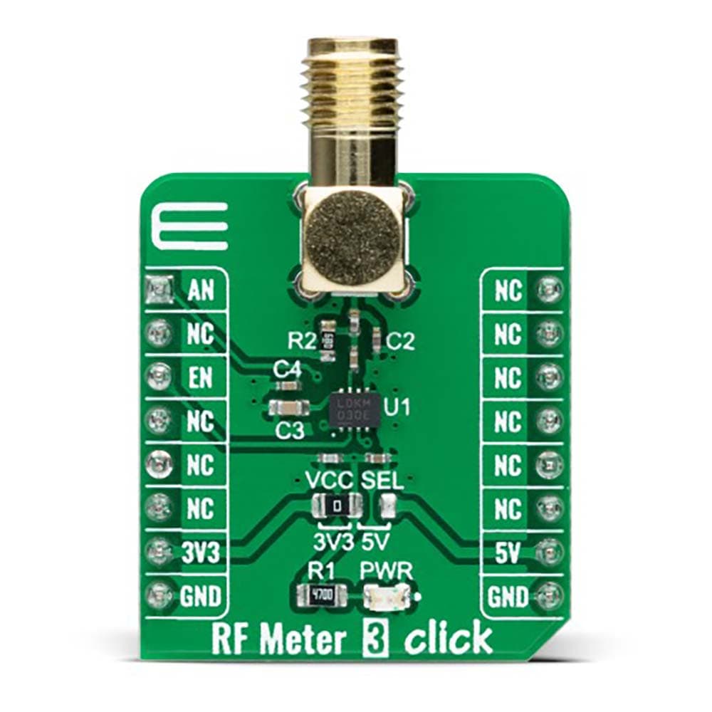
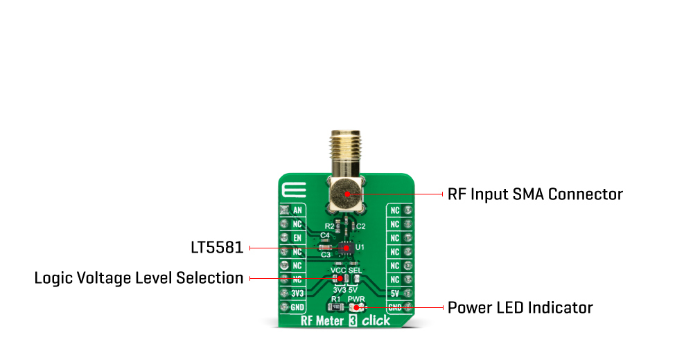
The RF Meter 3 Click Board™ is a compact add-on board that collects information, analyzes RF power, and displays information in an easy-to-read digital format. This board features the LT5581, a low-power monolithic precision RMS power detector from Analog Devices. The RMS detector uses a proprietary technique to accurately measure the RF power in a range from 2GHz up to 2.6GHz, well-suited for signals with high crest factors. It outputs a DC voltage in linear scale proportional to an RF input signal power in dBm. This Click board™ is suitable for precision power measurement and control for various RF standards, including GSM/EDGE, CDMA, CDMA2000, W-CDMA, TD-SCDMA, UMTS, LTE, and WiMAX.
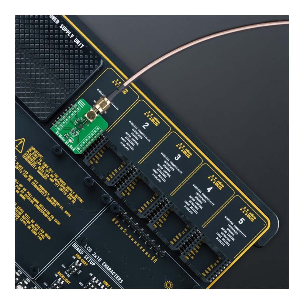
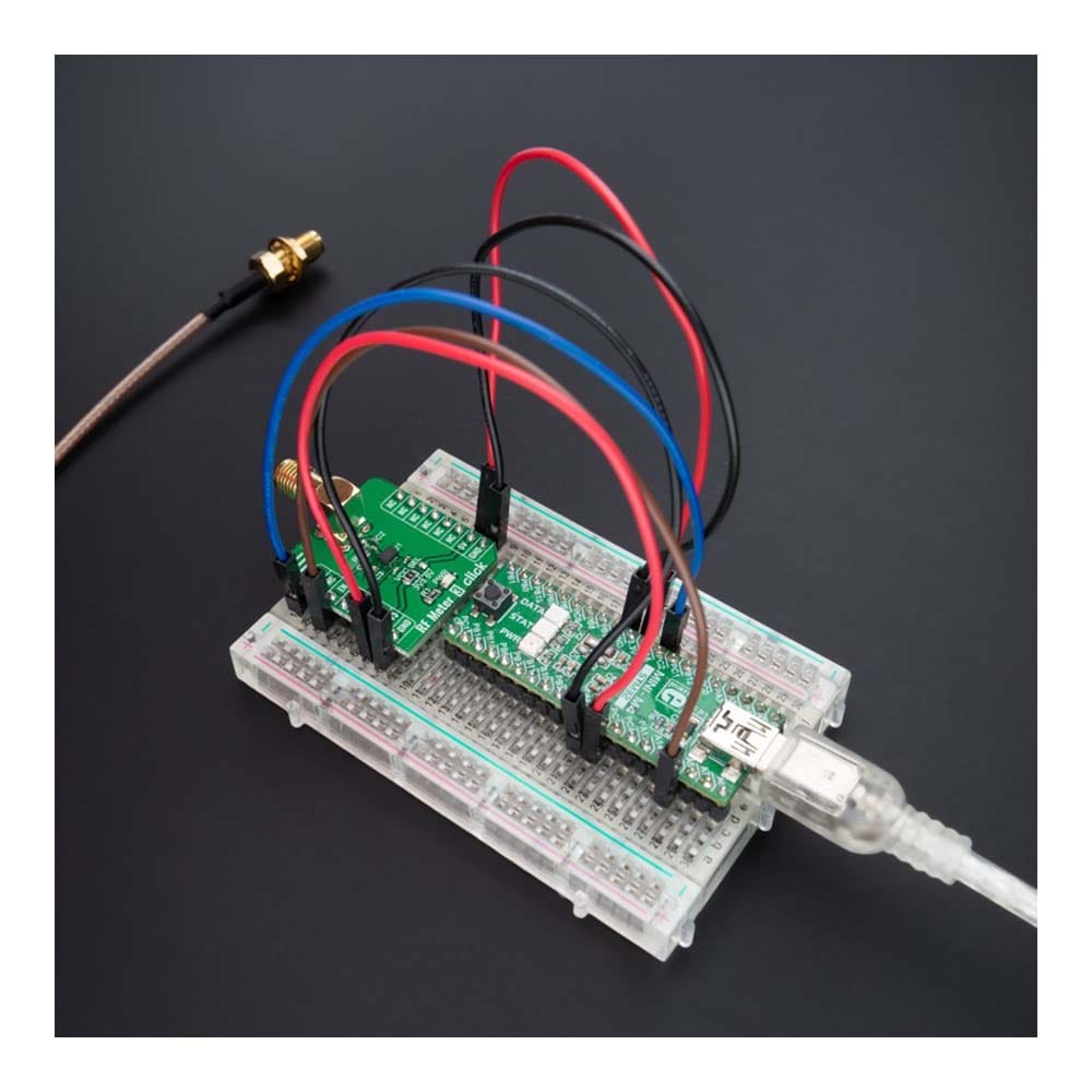
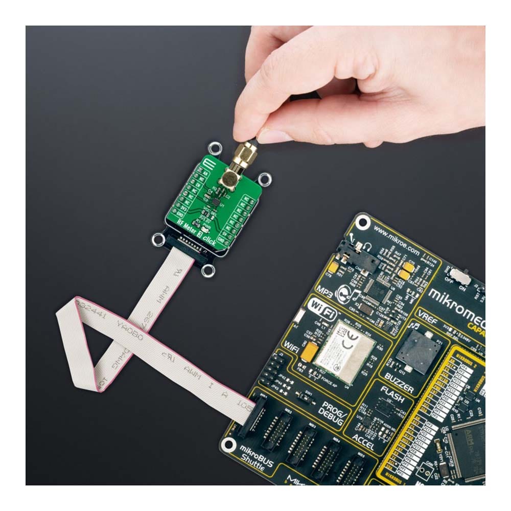
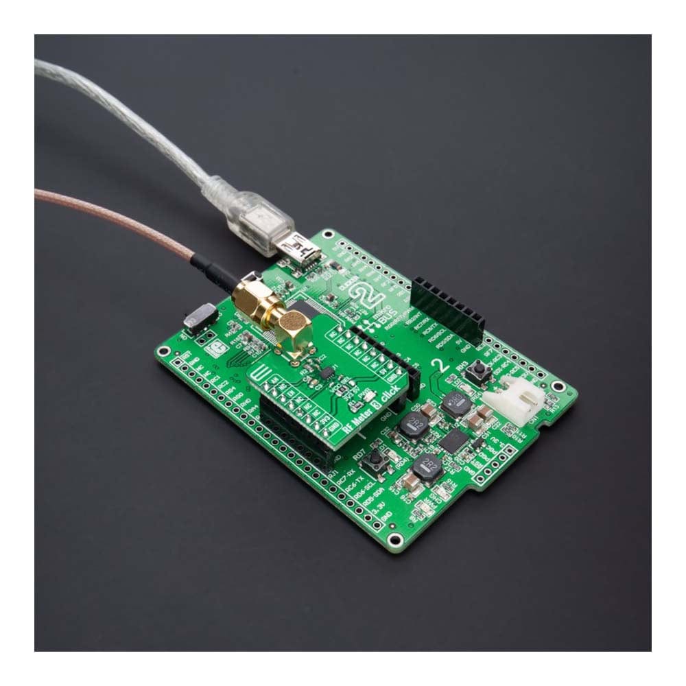
The RF Meter 3 Click Board™ is supported by a mikroSDK compliant library, which includes functions that simplify software development. This Click board™ comes as a fully tested product, ready to be used on a system equipped with the mikroBUS™ socket.
Downloads
How Does The RF Meter 3 Click Board™ Work?
The RF Meter 3 Click Board™ is based on the LT5581, RMS power detector with a 40dB dynamic range from Analog Devices. Users can use an RF power meter like this one to measure and document pulsed RF signals, noise-like signals, and pseudorandom signals. The RMS detector uses a proprietary technique to measure the RF power from 2GHz up to 2.6GHz accurately. Moreover, the LT5581 offers exceptional accuracy over its operating temperature range of -40°C to 85°C.
Its RMS measurement capability provides accurate RF power readings to within ±0.2dB regardless of waveforms with high crest-factor modulated content, multi-carrier or multitone. The LT5581 combines a proprietary high-speed power measurement subsystem with an internal 150kHz low pass averaging filter and an output voltage buffer in a completely integrated solution to achieve an accurate average power measurement of the high crest factor modulated RF signals. The resulting output voltage is directly proportional to the average RF input power in dBm.
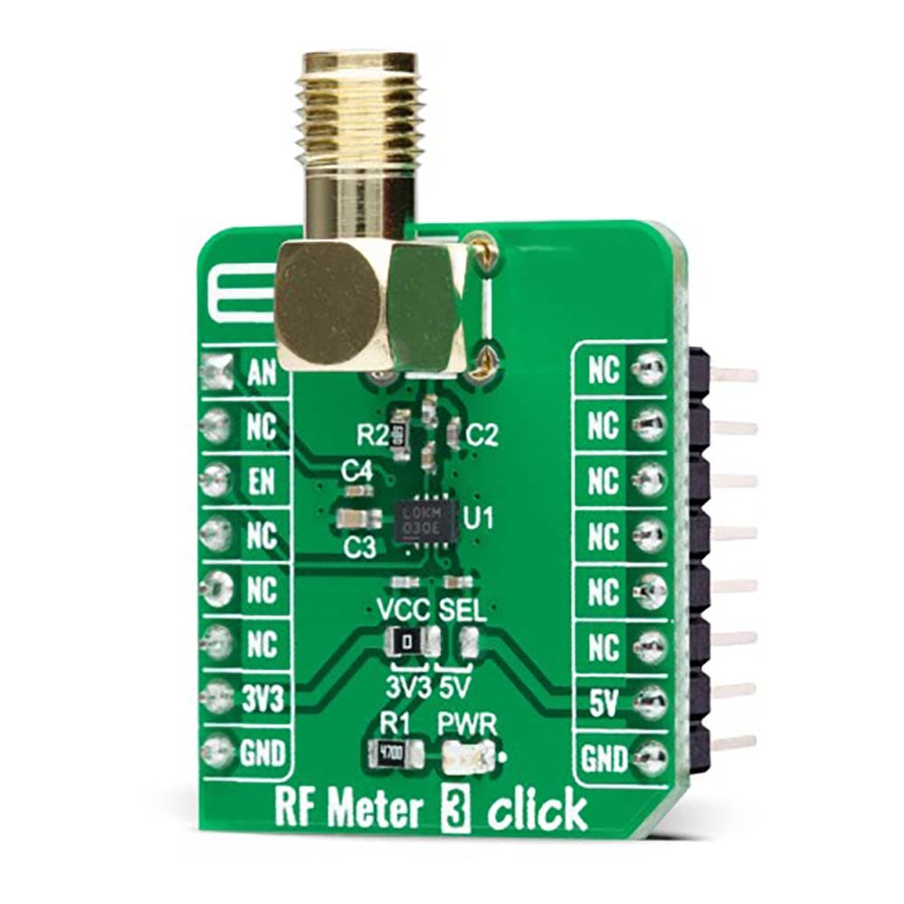
The RF Meter 3 Click Board™ uses two mikroBUS™ pins for direct control. The Enable pin, labelled as EN and routed to the CS pin of the mikroBUS™ socket, optimizes power consumption and is used for power ON/OFF purposes (Shutdown feature). When its Enable input pin is pulled low, the LT5581 draws a typical shutdown current of 0.2uA and a maximum of 6uA. As mentioned before, the resulting output voltage of the LT5581 is sent directly to an analog pin of the mikroBUS™ socket labelled as AN for MCU to read further and analyze RF signal data.
The RF Meter 3 Click Board™ can operate with both 3.3V and 5V logic voltage levels selected via the VCC SEL jumper. This way, it is allowed for both 3.3V and 5V capable MCUs to use the communication lines properly. However, the Click board™ comes equipped with a library containing easy-to-use functions and an example code that can be used, as a reference, for further development.
SPECIFICATIONS
| Type | RF meter |
| Applications | The RF Meter 3 Click Board™ can be used for precision power measurement and control for various RF standards |
| On-board modules | LT5581 - RMS power detector with a 40dB dynamic range from Analog Devices |
| Key Features | Accurate power measurement of high crest factor waveforms, 40dB log linear dynamic range, exceptional accuracy over temperature, low power consumption, log-linear DC output vs input RF power in dBm, and more |
| Interface | Analog |
| Compatibility | mikroBUS |
| Click board size | S (28.6 x 25.4 mm) |
| Input Voltage | 3.3V or 5V |
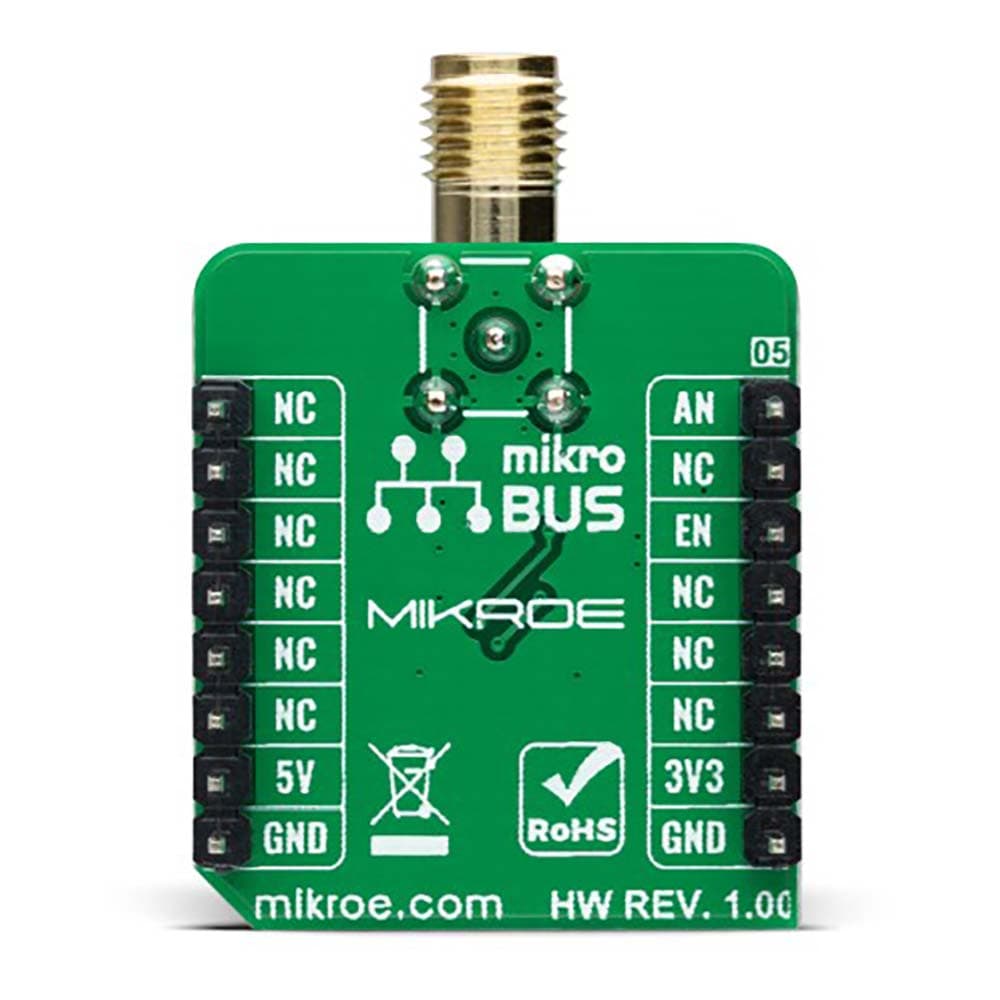
PINOUT DIAGRAM
This table shows how the pinout on RF Meter 3 Click corresponds to the pinout on the mikroBUS™ socket (the latter shown in the two middle columns).
| Notes | Pin | Pin | Notes | ||||
|---|---|---|---|---|---|---|---|
| Analog Signal | AN | 1 | AN | PWM | 16 | NC | |
| NC | 2 | RST | INT | 15 | NC | ||
| Enable | EN | 3 | CS | RX | 14 | NC | |
| NC | 4 | SCK | TX | 13 | NC | ||
| NC | 5 | MISO | SCL | 12 | NC | ||
| NC | 6 | MOSI | SDA | 11 | NC | ||
| Power Supply | 3.3V | 7 | 3.3V | 5V | 10 | 5V | Power Supply |
| Ground | GND | 8 | GND | GND | 9 | GND | Ground |
ONBOARD SETTINGS AND INDICATORS
| Label | Name | Default | Description |
|---|---|---|---|
| LD1 | PWR | - | Power LED Indicator |
| JP1 | VCC SEL | Left | Logic Level Voltage Selection 3V3/5V: Left position 3V3, Right position 5V |
RF METER 3 CLICK ELECTRICAL SPECIFICATIONS
| Description | Min | Typ | Max | Unit |
|---|---|---|---|---|
| Supply Voltage | 3.3 | - | 5 | V |
| Operating Frequency Range | 2 | - | 2.6 | GHz |
| Dynamic Range | - | 40 | - | dB |
| Accuracy | - | ±1 | - | dB |
| Operating Temperature Range | -40 | +25 | +85 | °C |
| General Information | |
|---|---|
Part Number (SKU) |
MIKROE-4906
|
Manufacturer |
|
| Physical and Mechanical | |
Weight |
0.02 kg
|
| Other | |
EAN |
8606027389351
|
Frequently Asked Questions
Have a Question?
Be the first to ask a question about this.