


Mikroelektronika d.o.o.
ISM RX 3 Click Board™
ISM RX 3 Click Board™
SKU: MIKROE-4828
Couldn't load pickup availability


Overview
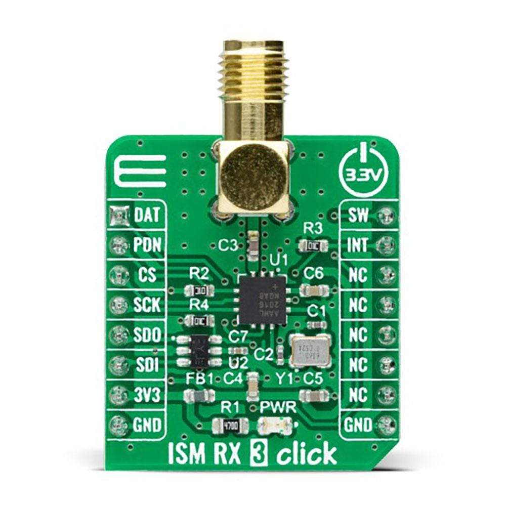
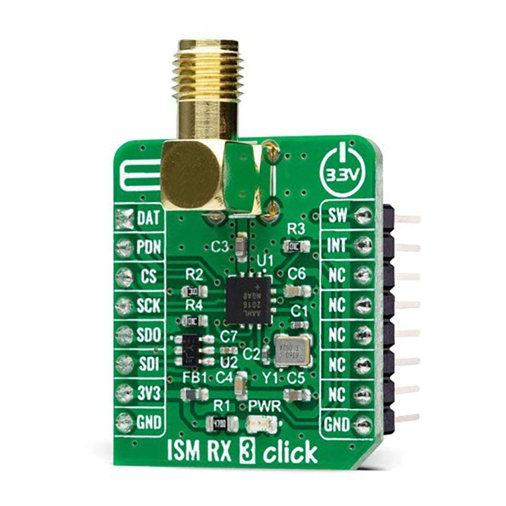
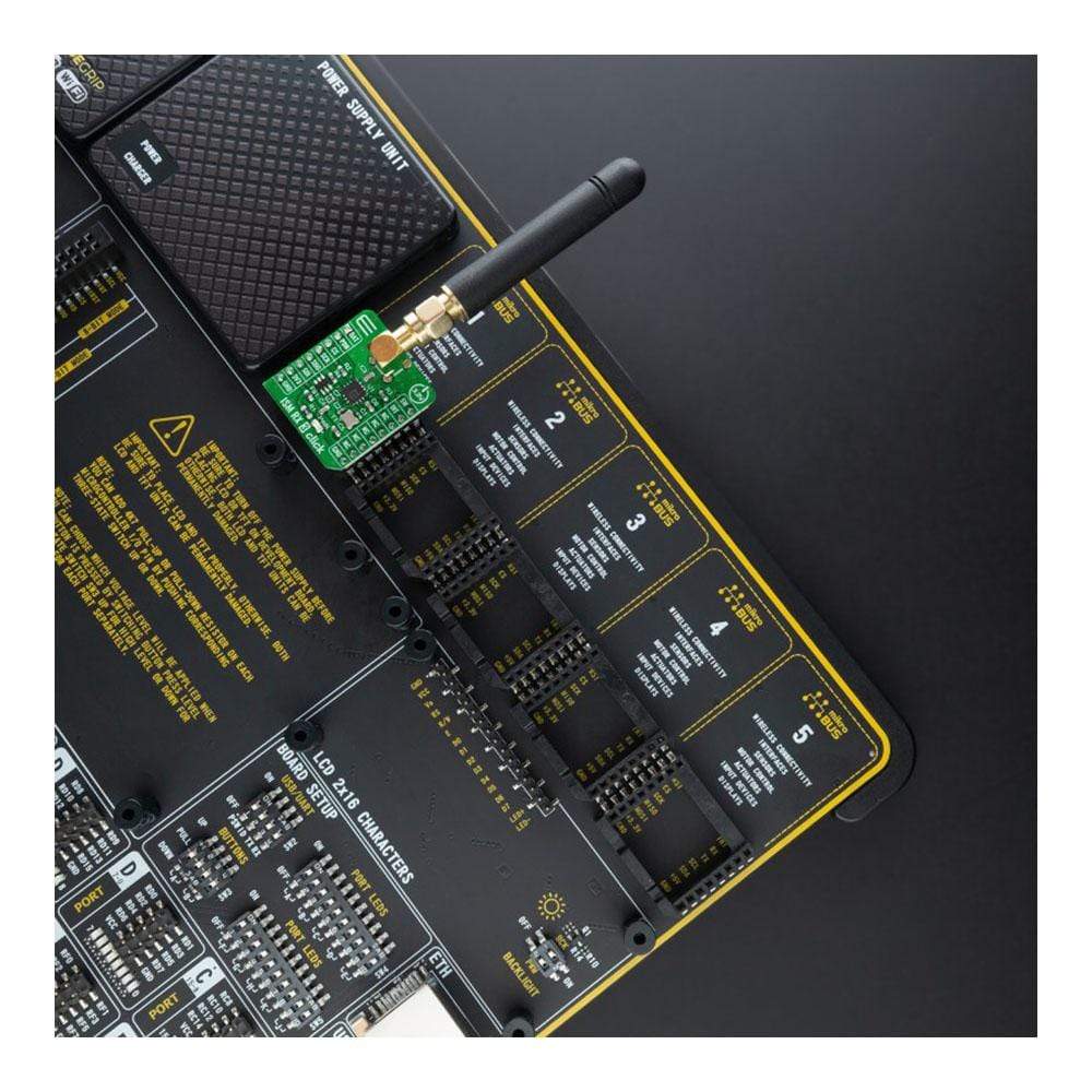
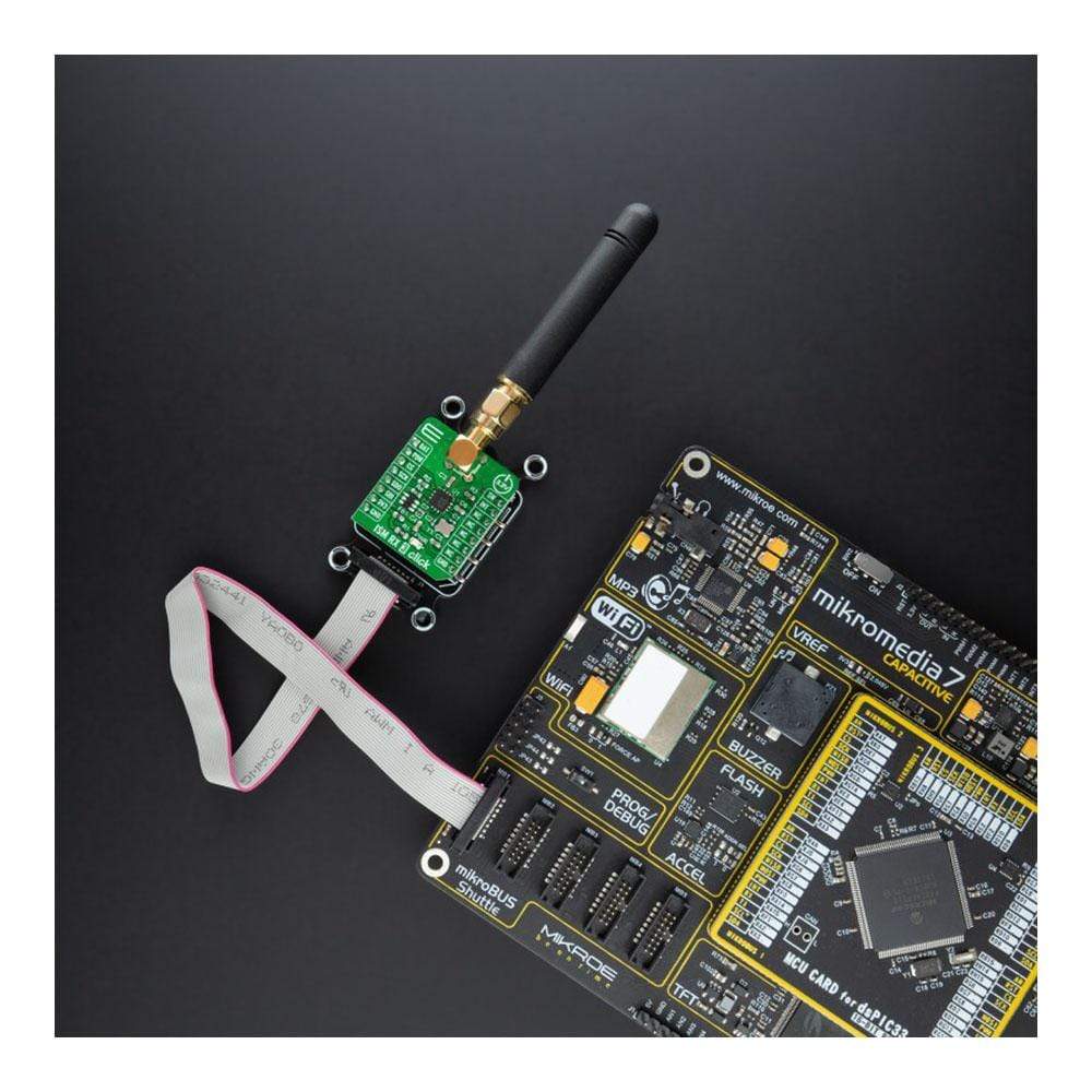
The ISM RX 3 Click Board™ is a compact add-on board that contains a Sub-GHz RF receiver. This board features the MAX41470, a high-performance, low-power receiver ideal for amplitude shift-keyed (ASK) and frequency shift-keyed (FSK) data from Maxim Integrated, now part of Analog Devices. It can be configured for three sub-1GHz bands using an onboard 16MHz crystal: 287MHz to 320MHz, 425MHz to 480MHz, and 860MHz to 960MHz, fully programmable through an SPI interface. The receiver has excellent RF sensitivity and long-range, allows input signals up to 0dBm of power at the RF input, and features a fully programmable, self-polling (duty cycling) mode with preamble detection and interrupt output to wake up an external MCU.
The ISM RX 3 Click Board™ is suitable for cost- and power-sensitive applications, such as home automation and security, building access control, remote keyless entry, garage or gate doors control, and similar applications.
Downloads
How does it work?
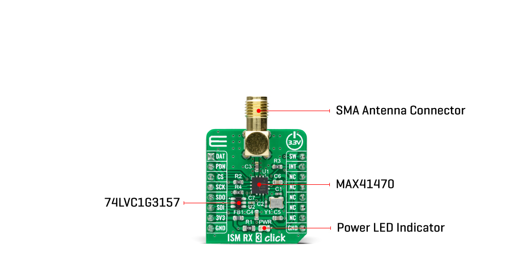
The ISM RX 3 Click Board™ is based on the MAX41470, a sub-GHz ISM RF receiver from Maxim Integrated, now part of Analog Devices. This IC is designed to receive ASK/OOK or FSK/GFSK modulated data in the 287MHz to 320MHz (nominally 315MHz), 425MHz to 480MHz (nominally 434MHz), and 860MHz to 960MHz (nominally 868MHz or 915MHz) ISM frequency bands, using an onboard 16MHz crystal. The ISM RX 3 Click Board™ comes with an ASK modulation and 433.92MHz with a 5bps data rate as its default configuration. Its additional features also include automatic gain control (AGC), a received signal strength indicator (RSSI), automatic frequency control (AFC), and a frequency error indicator (FEI).
The MAX41470 has four power states: Shutdown, Sleep, Standby, and Receive-Active. Its Power-Down pin, labeled as PDN and routed to the RST pin of the mikroBUS™ socket, optimizes power consumption used for power ON/OFF purposes. When the device is enabled (the PDN pin set to a low logic state), the device operational states are controlled through the serial interface by the internal registers.
The ISM RX 3 Click Board™ communicates with MCU through a standard SPI interface that enables very high clock speeds up to 20MHz, supporting the most common SPI mode, SPI Mode 3 to program the internal registers for complete control of the MAX41470. When in programming mode, the MAX41470 can support a self-polling operation to provide an interrupt signal on the DAT pin routed to the AN pin of the mikroBUS™ socket.
The MAX41470 comes only with one data pin for register programming, both data input/output pin. For that purpose, this Click board™ uses the 74LVC1G3157 multiplexer to avoid conflict with other functions driven by the same pin, enabling both writing and reading via the SPI interface and using the 4-wire SPI interface. The selection of the multiplexer channel, more precisely the MISO or MOSI line, is chosen by a logic level on the S line of the multiplexer, set by an SW pin routed to the PWM pin of the mikroBUS™ socket.
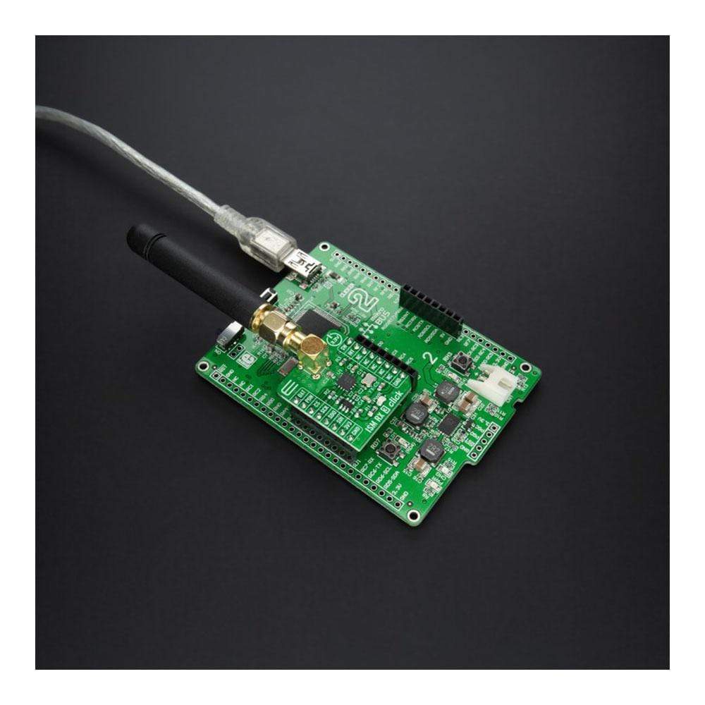
The ISM RX 3 Click Board™ possesses the SMA antenna connector with an impedance of 50Ω, which can use it to connect the appropriate antenna that Mikroe has in its offer for improved range and received signal strength.
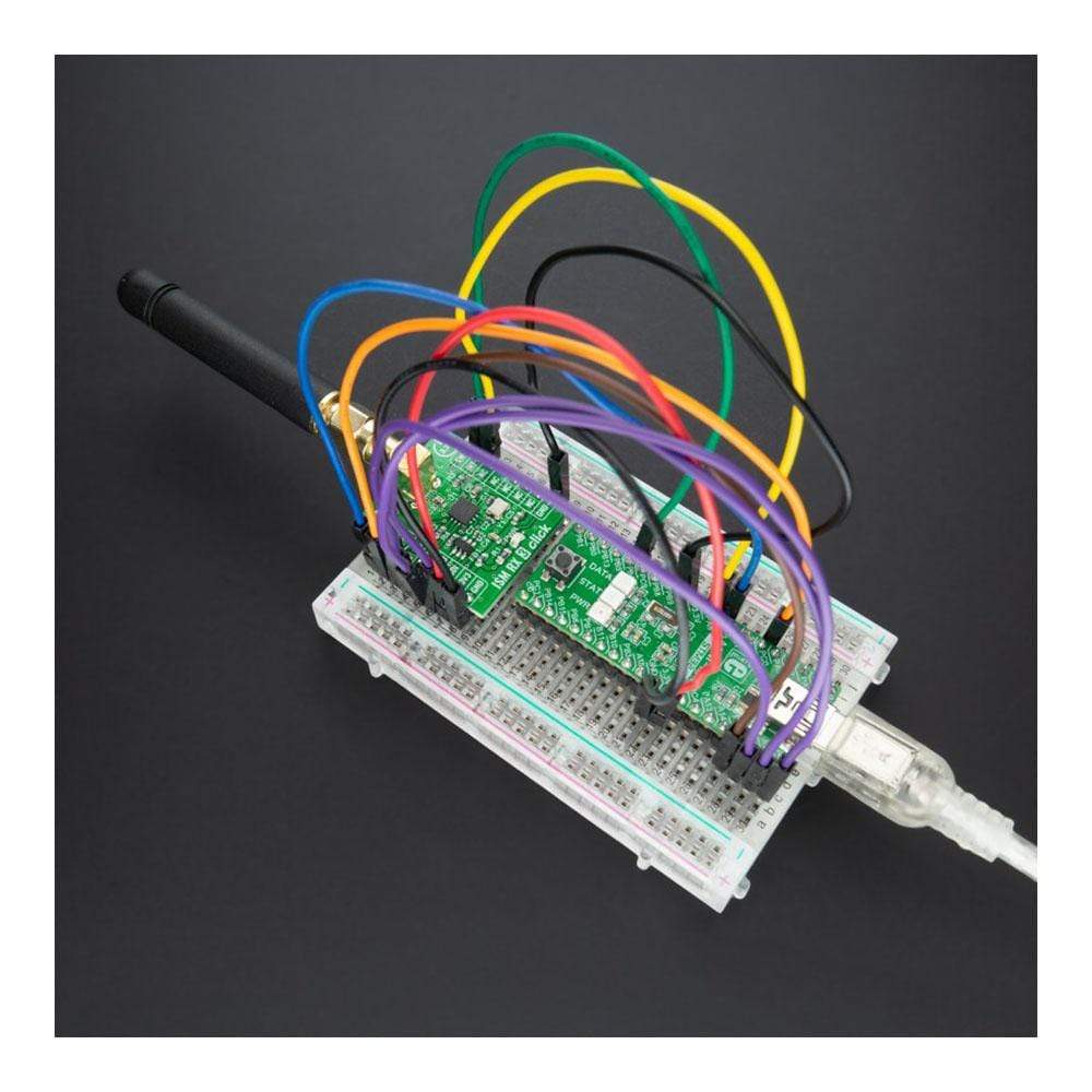
This Click board™ can be operated only with a 3.3V logic voltage level. The board must perform appropriate logic voltage level conversion before use with MCUs with different logic levels. However, the Click board™ comes equipped with a library containing functions and an example code that can be used, as a reference, for further development.
Specifications
| Type | Sub-1 GHz Transceivers |
| Applications | Can be used for home automation and security, building access control, remote keyless entry, garage or gate doors control, and similar applications |
| On-board modules | MAX41470 - sub-GHz ISM RF receiver from Maxim Integrated, now part of Analog Devices |
| Key Features | Long-range with high sensitivity, low power consumption, high performance, self-polling (remote wake-up) for reduced power, gain and frequency control, and more |
| Interface | SPI |
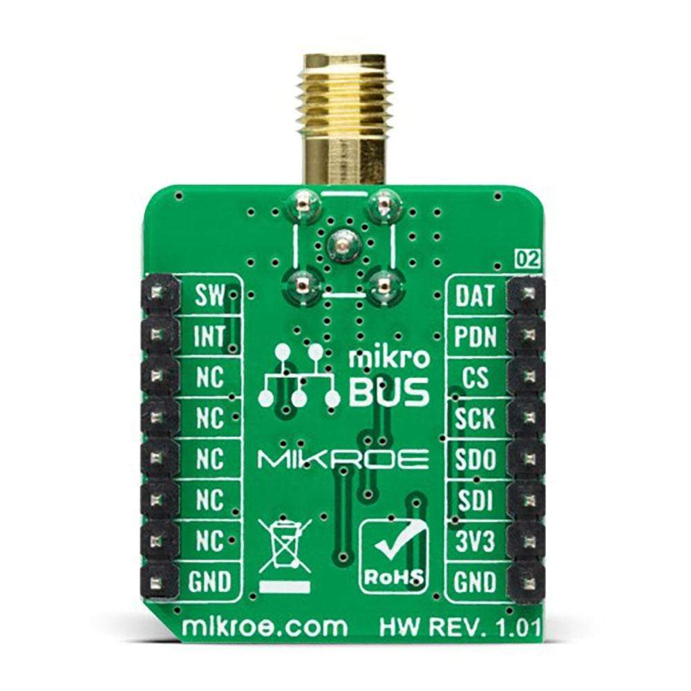
| Compatibility | mikroBUS |
| Click board size | S (28.6 x 25.4 mm) |
| Input Voltage | 3.3V |
Pinout Diagram
This table shows how the pinout on the ISM RX 3 Click Board™ corresponds to the pinout on the mikroBUS™ socket (the latter shown in the two middle columns).
| Notes | Pin | Pin | Notes | ||||
|---|---|---|---|---|---|---|---|
| Demodulated Received Signal Data | DAT | 1 | AN | PWM | 16 | SW | MISO/MOSI Channel Selection |
| Power-Down (Enable) | PDN | 2 | RST | INT | 15 | INT | Recovered Clock |
| SPI Chip Select | CS | 3 | CS | RX | 14 | NC | |
| SPI Clock | SCK | 4 | SCK | TX | 13 | NC | |
| SPI Data OUT | SDO | 5 | MISO | SCL | 12 | NC | |
| SPI Data IN | SDI | 6 | MOSI | SDA | 11 | NC | |
| Power Supply | 3.3V | 7 | 3.3V | 5V | 10 | NC | |
| Ground | GND | 8 | GND | GND | 9 | GND | Ground |
Onboard settings and indicators
| Label | Name | Default | Description |
|---|---|---|---|
| LD1 | PWR | - | Power LED Indicator |
ISM RX 3 Click electrical specifications
| Description | Min | Typ | Max | Unit |
|---|---|---|---|---|
| Supply Voltage | - | 3.3 | - | V |
| Frequency Range | 287 | - | 320 | MHz |
| 425 | - | 480 | ||
| 860 | - | 960 | ||
| Data Rate | - | 200 | - | kbps |
| Sensitivity | - | -127 | - | dBm |
| Operating Temperature Range | -40 | +25 | +105 | °C |
| General Information | |
|---|---|
Part Number (SKU) |
MIKROE-4828
|
Manufacturer |
|
| Physical and Mechanical | |
Weight |
0.02 kg
|
| Other | |
EAN |
8606027383908
|
Frequently Asked Questions
Have a Question?
Be the first to ask a question about this.