


Mikroelektronika d.o.o.
LDC 2 Click Board™
LDC 2 Click Board™
SKU: MIKROE-4783
Couldn't load pickup availability


Overview
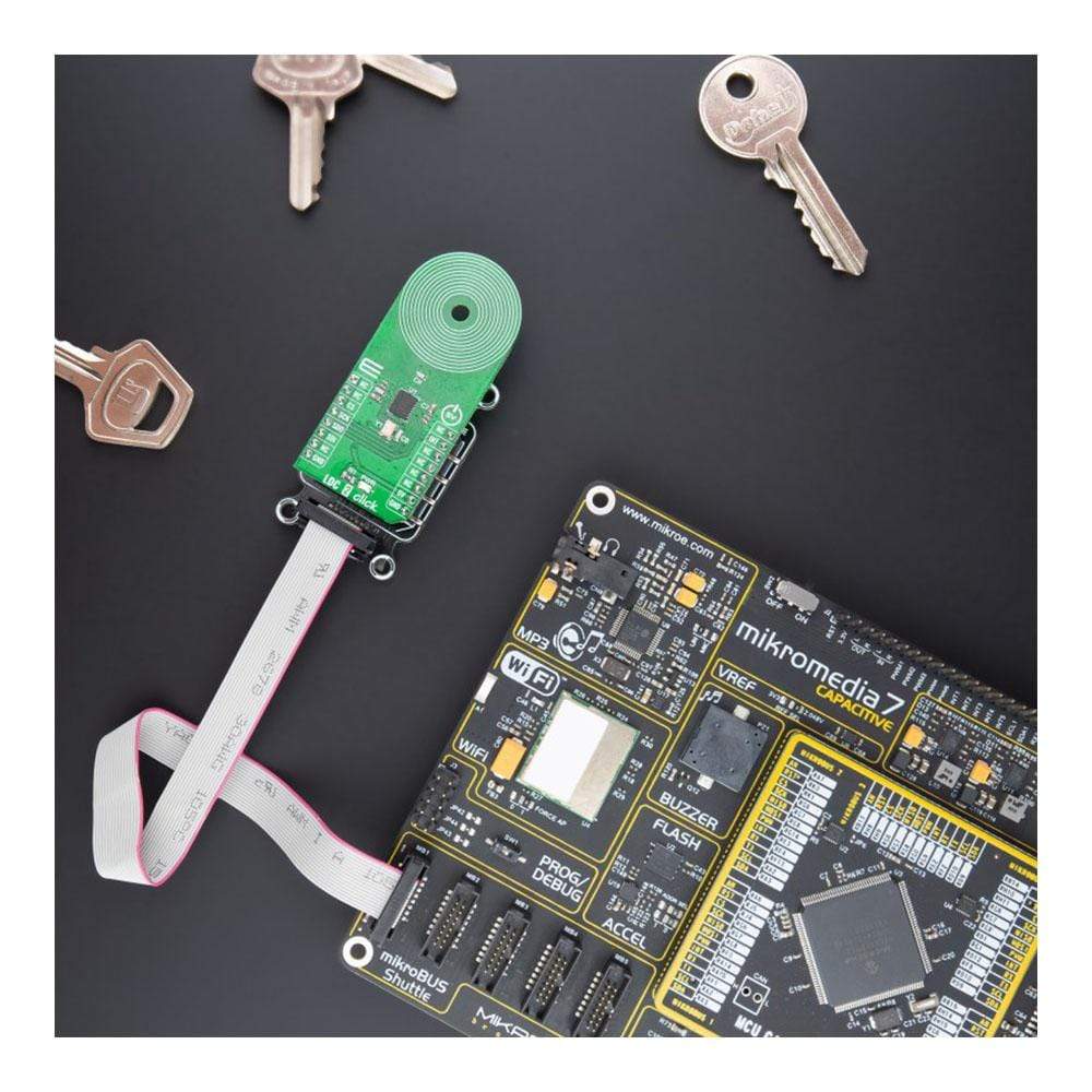
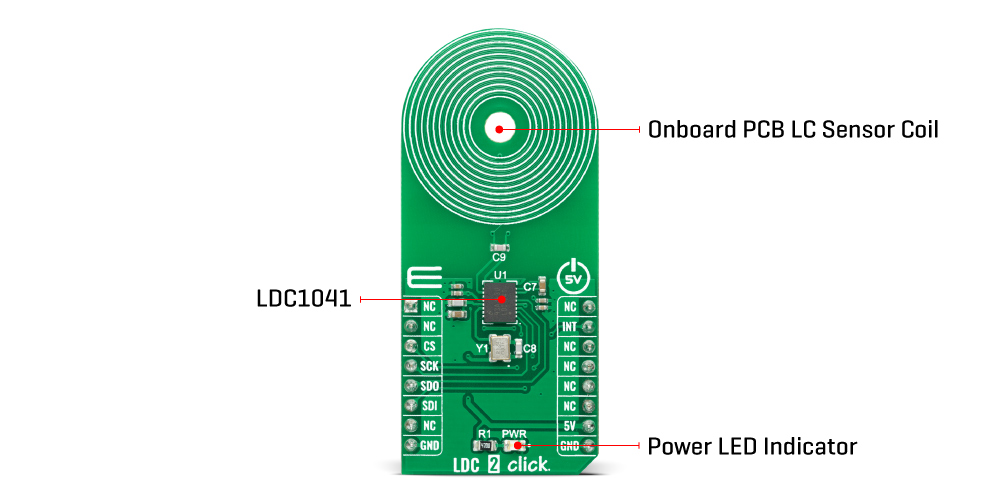
The LDC 2 Click Board™ is a compact add-on board that measures inductance change which a conductive target causes when it moves into the inductor's AC magnetic field. This board features the LDC1041, inductance-to-digital converter (LDC) for inductive sensing solutions from Texas Instruments. This Click Board™ is easy-to-use, requiring only the sensor frequency within 5kHz and 5MHz to begin sensing, and demonstrates the use of inductive sensing technology to sense and measure a conductive target object's presence, position, or composition. It comes with an example of a PCB sensor coil designed to provide the user with maximum flexibility. This Click Board™ is suitable for contactless, short-range sensing that enables high-resolution and low-cost position sensing of conductive targets, even in harsh environments.
The LDC 2 Click Board™ is supported by a mikroSDK compliant library, which includes functions that simplify software development. This Click Board™ comes as a fully tested product, ready to be used on a system equipped with the mikroBUS™ socket.
Downloads
How Does The LDC 2 Click Board™ Work?
The LDC 2 Click Board™ as its foundation uses the LDC1041, an inductance-to-digital converter that simultaneously measures an LC resonator's impedance and resonant frequency from Texas Instruments. This Click board™ is easy-to-use, requiring only the sensor frequency within 5kHz and 5MHz to begin sensing, and demonstrates the use of inductive sensing technology to sense and measure a conductive target object's presence, position, or composition. In addition, the LDC1041 also measures the oscillation frequency of the LC circuit, used to determine the inductance of the LC circuit. The device then outputs a digital value that is inversely proportional to frequency.
The LDC measures the inductance change that a conductive target causes when it moves into the inductor's AC magnetic field to provide information about the target's position over a sensor coil. The inductance shift is caused by eddy currents (circulating currents) generated in the target due to the sensor's magnetic field. These eddy currents generate a secondary magnetic field that opposes the sensor field, causing a shift in the observed inductance, used for precise positioning of the target as it moves laterally over the sensor coil.
Also, the LDC1041 has two power modes: Active and Standby Mode. In Active Mode, the proximity data and frequency data conversion are enabled, while Standby mode represents the default mode on devices' Power-Up sequence. In Standby Mode, the conversion process is disabled. This Click board™ comes with an example of a PCB sensor coil designed to provide the user with maximum flexibility.
The LDC1041 communicates with MCU using the standard SPI serial interface with a maximum frequency of 4MHz. In addition to this serial interface, one GPIO pin connected to the mikroBUS™ socket is also used. The configurable interrupt pin, routed to the INT pin of the mikroBUS™ socket, may be configured in three different ways by programming the interrupt Terminal mode register with SPI. An interrupt pin provides the ability to act as a proximity switch, as a wake-up feature, or as a data-ready pin indicating a valid condition for new data availability.
The LDC 2 Click Board™ operates only with a 5V logic voltage level. The board must perform appropriate logic voltage level conversion before use with MCUs with different logic levels. However, the Click board™ comes equipped with a library containing functions and an example code that can be used, as a reference, for further development.
Specifications
| Type | Inductance |
| Applications | Can be used for contactless, short-range sensing that enables high-resolution and low-cost position sensing of conductive targets, even in harsh environments. |
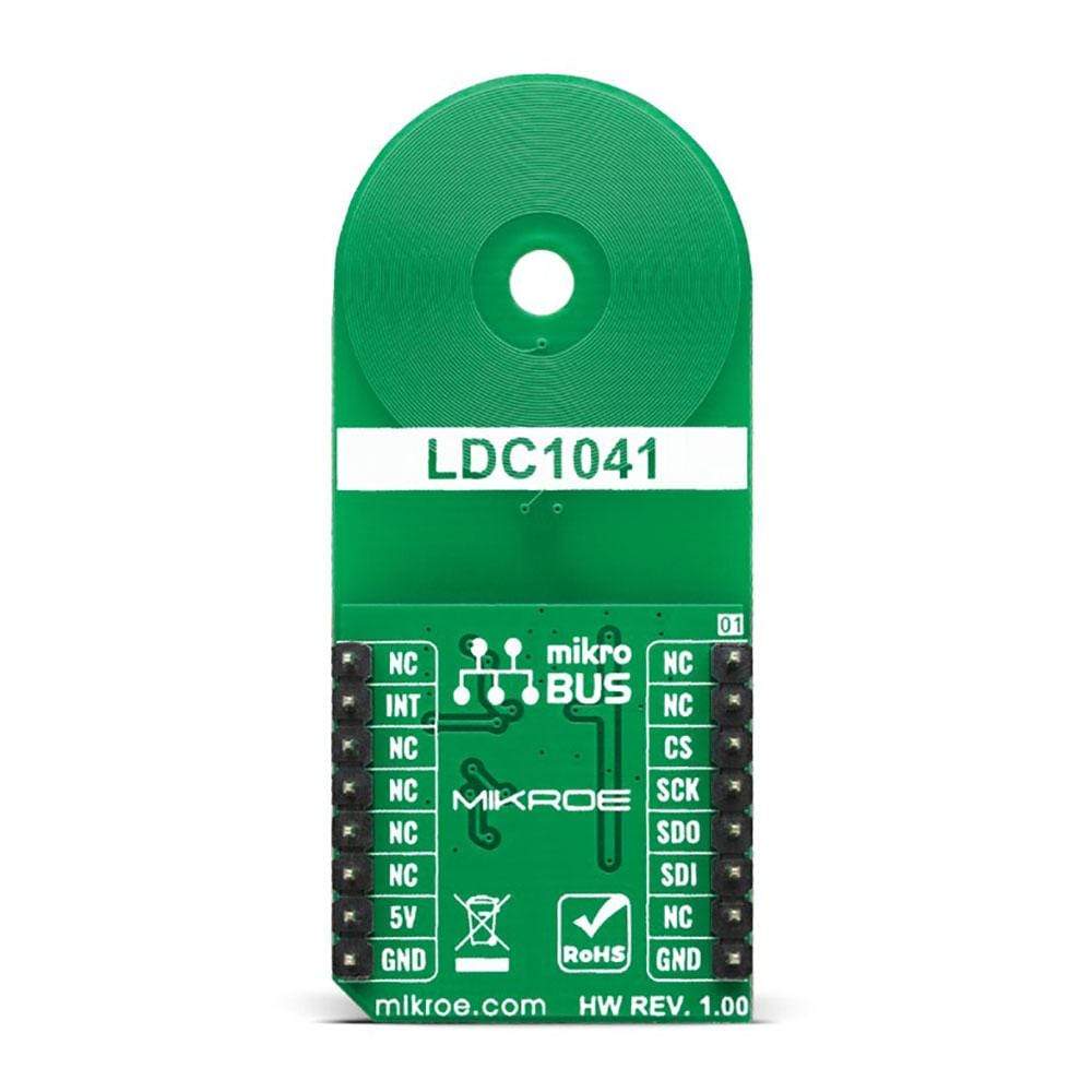
| On-board modules | LDC1041 - inductance-to-digital converter that simultaneously measures an LC resonator's impedance and resonant frequency from Texas Instruments |
| Key Features | Low power consumption, short-range sensing technology, high durability, high flexibility, supports a wide frequency range from 5kHz to 5MHz, high performance, reliability, and more |
| Interface | SPI |
| Compatibility | mikroBUS |
| Click board size | L (57.15 x 25.4 mm) |
| Input Voltage | 5V |
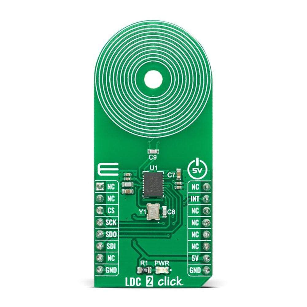
Pinout diagram
This table shows how the pinout on the LDC 2 Click Board™corresponds to the pinout on the mikroBUS™ socket (the latter shown in the two middle columns).
| Notes | Pin | Pin | Notes | ||||
|---|---|---|---|---|---|---|---|
| NC | 1 | AN | PWM | 16 | NC | ||
| NC | 2 | RST | INT | 15 | INT | Interrupt | |
| SPI Chip Select | CS | 3 | CS | RX | 14 | NC | |
| SPI Clock | SCK | 4 | SCK | TX | 13 | NC | |
| SPI Data OUT | SDO | 5 | MISO | SCL | 12 | NC | |
| SPI Data IN | SDI | 6 | MOSI | SDA | 11 | NC | |
| NC | 7 | 3.3V | 5V | 10 | 5V | Power Supply | |
| Ground | GND | 8 | GND | GND | 9 | GND | Ground |
Onboard settings and indicators
| Label | Name | Default | Description |
|---|---|---|---|
| LD1 | PWR | - | Power LED Indicator |
LDC 2 Click electrical specifications
| Description | Min | Typ | Max | Unit |
|---|---|---|---|---|
| Supply Voltage | - | 5 | - | V |
| Sensor Frequency | 5 | - | 5000 | kHz |
| Inductance Measurement Resolution | - | 24 | - | bits |
| Operating Temperature Range | -40 | +25 | +125 | °C |
| General Information | |
|---|---|
Part Number (SKU) |
MIKROE-4783
|
Manufacturer |
|
| Physical and Mechanical | |
Weight |
0.02 kg
|
| Other | |
EAN |
8606027383724
|
Frequently Asked Questions
Have a Question?
Be the first to ask a question about this.