


Mikroelektronika d.o.o.
Ambient 10 Click Board™
Ambient 10 Click Board™
SKU: MIKROE-4777
Couldn't load pickup availability
Overview
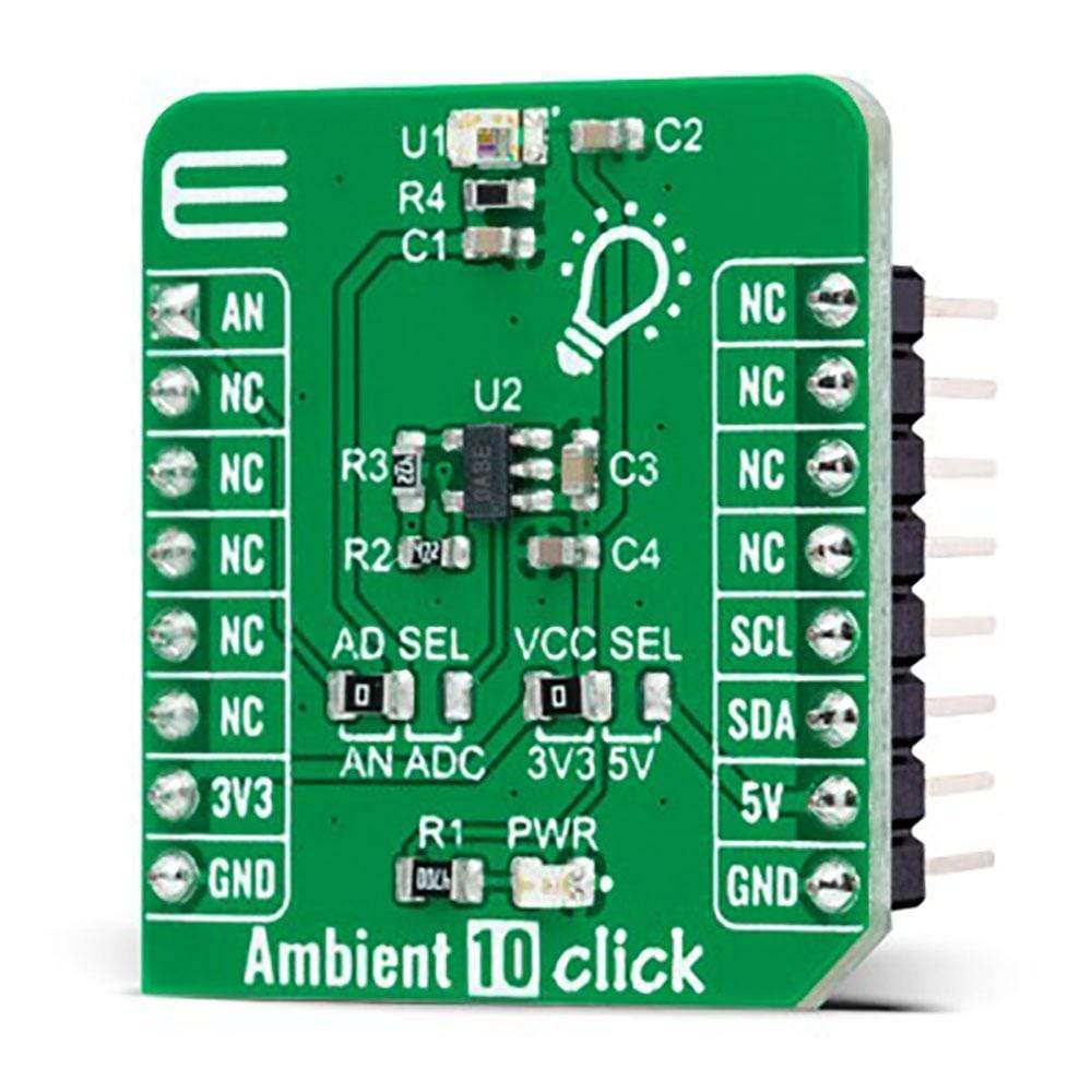
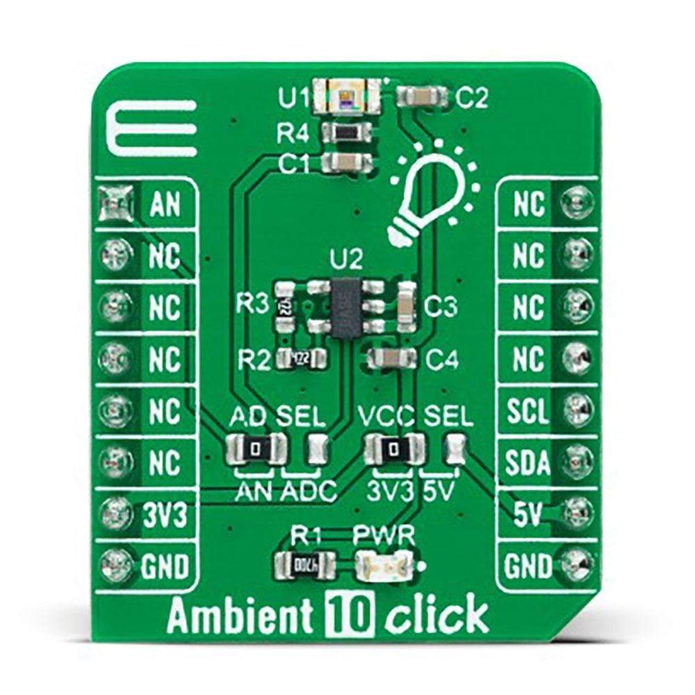
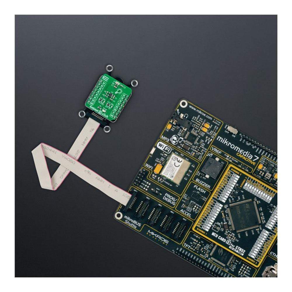
The Ambient 10 Click Board™ is a compact add-on board used to sense the amount of the present ambient light. This board features the APDS-9006-020, an analogue-output ambient light photosensor from Broadcom Limited. It consists of a spectrally suited photosensor, which provides excellent responsivity that is close to the response of the human eyes. Besides, it is also characterized by good output linearity across a wide illumination range, low sensitivity variation across various light sources, and comes with the ability to process the output signal in analogue or digital form. This Click Board™ is the most suitable for obtaining ambient light data for adjusting brightness in applications that require power saving and better visibility.
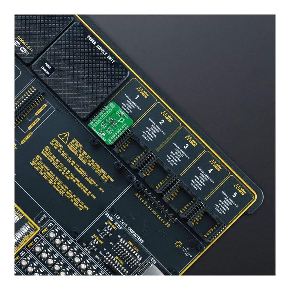
The Ambient 10 Click Board™ is supported by a mikroSDK compliant library, which includes functions that simplify software development. This Click Board™ comes as a fully tested product, ready to be used on a system equipped with the mikroBUS™ socket.
Downloads
How Does The Ambient 10 Click Board™ Work?
The Ambient 10 Click Board™ as its foundation uses the APDS-9006-020, analog-output ambient light photo sensor from Broadcom Limited. It consists of a photosensor whose spectral response is close to CIE standard photopic observer. Hence, it provides an excellent responsivity that is close to the response of human eyes. It has stable performance over a wide temperature and voltage range. It is characterized by good output linearity across a wide illumination range and low sensitivity variation across various light sources suitable to sense the amount of the present ambient light.
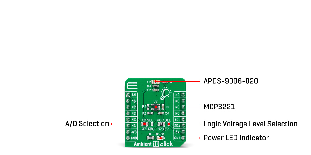
The analog output signal of the APDS-9006-020 can be converted to a digital value using MCP3221, a successive approximation A/D converter with a 12-bit resolution from Microchip, using a 2-wire I2C compatible interface, or can be sent directly to an analog pin of the mikroBUS™ socket labeled as AN. Selection can be performed by onboard SMD jumper labeled as A/D SEL to an appropriate position marked as AN and ADC.
The MCP3221 provides one single-ended input with low power consumption, a low maximum conversion current, and a Standby current of 250μA and 1μA, respectively. Data can be transferred at rates of up to 100kbit/s in the Standard and 400kbit/s in the Fast Mode. Also, maximum sample rates of 22.3kSPS with the MCP3221 are possible in a Continuous-Conversion Mode with a clock rate of 400kHz.
The Ambient 10 Click Board™ can operate with both 3.3V and 5V logic voltage levels selected via the VCC SEL jumper. This way, it is allowed for both 3.3V and 5V capable MCUs to use the communication lines properly. However, the Click board™ comes equipped with a library containing easy-to-use functions and an example code that can be used, as a reference, for further development.
Specifications
| Type | Optical |
| Applications | Can be used for obtaining ambient light data for adjusting brightness in applications that require power saving and better visibility |
| On-board modules | APDS-9006-020 - analog-output ambient light photosensor from Broadcom Limited |
| Key Features | Low power consumption, excellent responsivity which peaks in the human luminosity curve, close responsivity to the human eye, good output linearity across wide illumination range, low sensitivity variation across various light sources, stable performance over temperature and voltage, and more |
| Interface | Analog,I2C |
| Compatibility | mikroBUS |
| Click board size | S (28.6 x 25.4 mm) |
| Input Voltage | 3.3V or 5V |
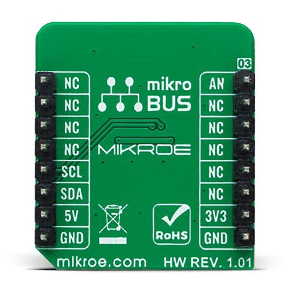
Pinout diagram
This table shows how the pinout of the Ambient 10 Click Board™ corresponds to the pinout on the mikroBUS™ socket (the latter shown in the two middle columns).
| Notes | Pin | Pin | Notes | ||||
|---|---|---|---|---|---|---|---|
| Analog Signal | AN | 1 | AN | PWM | 16 | NC | |
| NC | 2 | RST | INT | 15 | NC | ||
| NC | 3 | CS | RX | 14 | NC | ||
| NC | 4 | SCK | TX | 13 | NC | ||
| NC | 5 | MISO | SCL | 12 | SCL | I2C Clock | |
| NC | 6 | MOSI | SDA | 11 | SDA | I2C Data | |
| Power Supply | 3.3V | 7 | 3.3V | 5V | 10 | 5V | Power Supply |
| Ground | GND | 8 | GND | GND | 9 | GND | Ground |
Onboard settings and indicators
| Label | Name | Default | Description |
|---|---|---|---|
| LD1 | PWR | - | Power LED Indicator |
| JP1 | VCC SEL | Left | Logic Level Voltage Selection 3V3/5V: Left position 3V3, Right position 5V |
| JP2 | AD SEL | Left | Output Voltage A/D Selection AN/ADC: Left position AN, Right position ADC |
Ambient 10 Click electrical specifications
| Description | Min | Typ | Max | Unit |
|---|---|---|---|---|
| Supply Voltage | 3.3 | - | 5 | V |
| Peak Wavelength | - | 500 | - | nm |
| Operating Temperature Range | -40 | +25 | +85 | °C |
| General Information | |
|---|---|
Part Number (SKU) |
MIKROE-4777
|
Manufacturer |
|
| Physical and Mechanical | |
Weight |
0.02 kg
|
| Other | |
EAN |
8606027383588
|
Frequently Asked Questions
Have a Question?
Be the first to ask a question about this.