


Mikroelektronika d.o.o.
ISO ADC 5 Click Board™
ISO ADC 5 Click Board™
SKU: MIKROE-4758
Couldn't load pickup availability
Overview
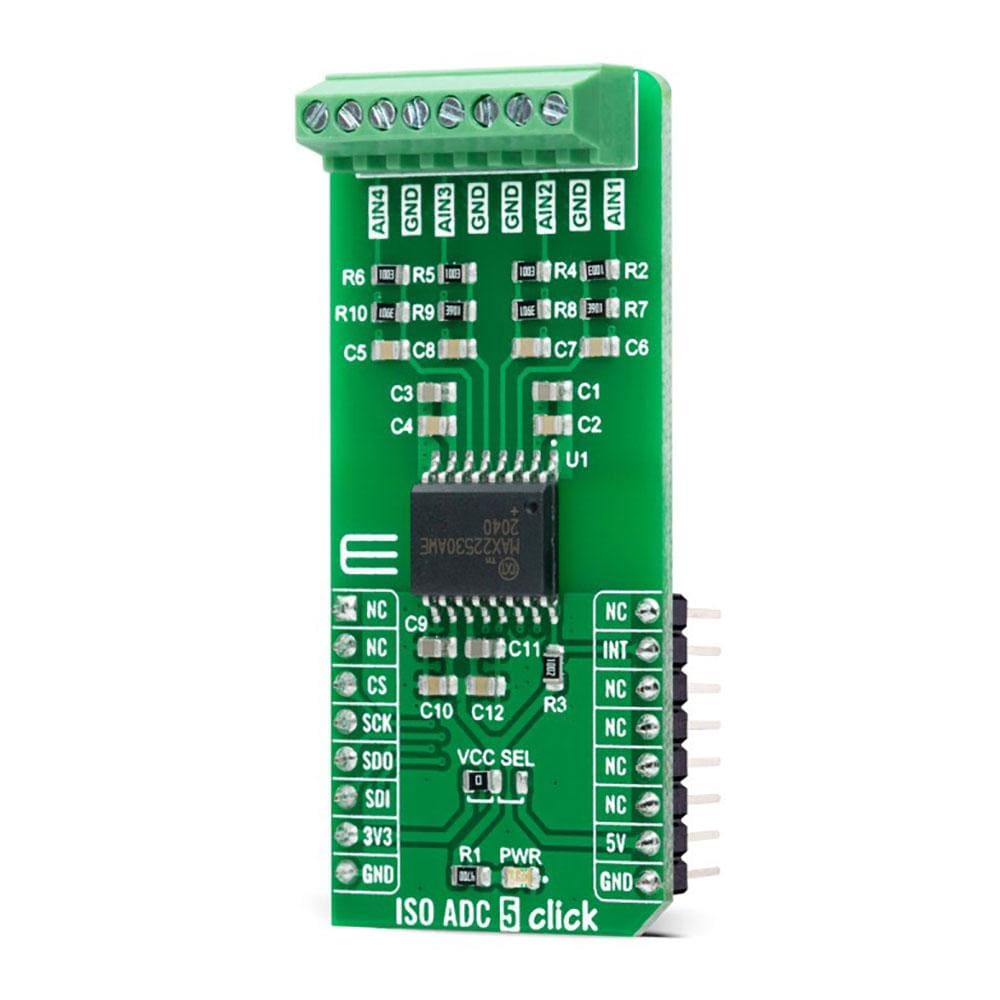
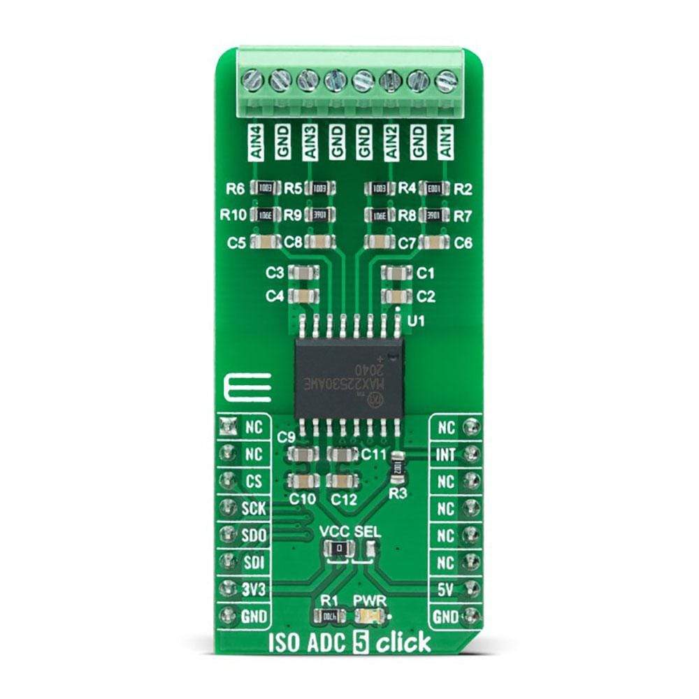
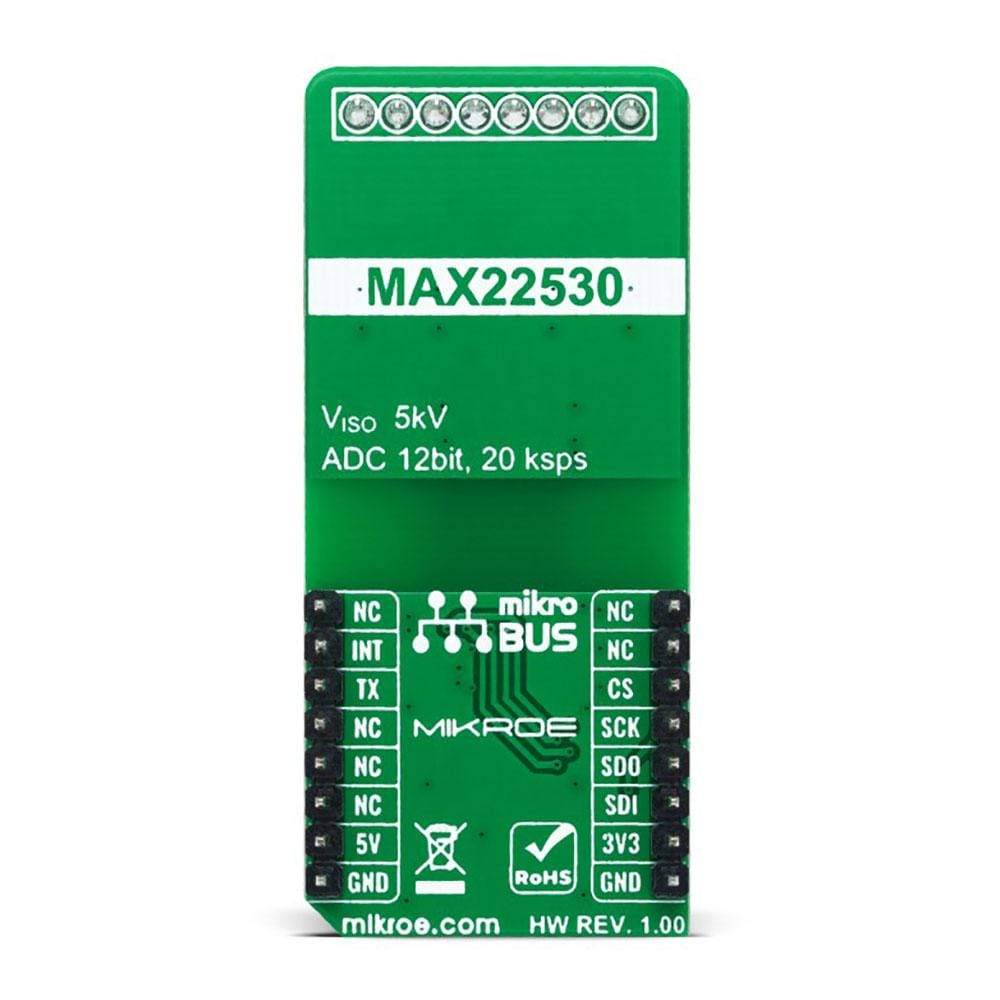
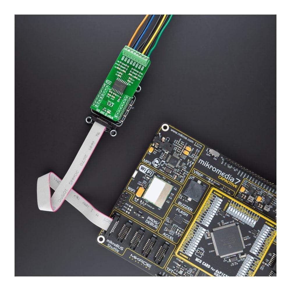
The ISO ADC 5 Click Board™ is a compact add-on board that contains quad-channel isolated ADC with field supply. This board features the MAX22530, galvanically isolated, 4-channel, multiplexed, 12-bit, analogue-to-digital converter (ADC), providing 5kVRMS isolation from Maxim Integrated. The ADC and all field-side circuits are powered by an integrated, isolated DC-DC converter that can verify field-side functionality even when there is no input signal or other field-side supply. The 12-bit ADC core has a sample rate of typically 20ksps per channel, where ADC data is available through the SPI interface. This Click Board™ is ideal for high-density, multi-range, group-isolated, binary-input modules and provides a complete solution to any system requiring monitoring inputs without a separate isolated power supply.
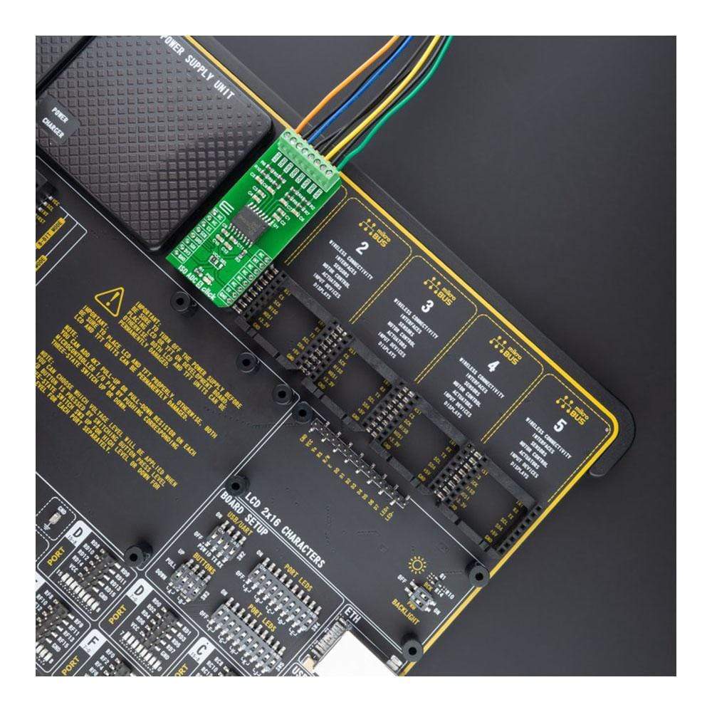
The ISO ADC 5 Click Board™ is supported by a mikroSDK compliant library, which includes functions that simplify software development. This Click Board™ comes as a fully tested product, ready to be used on a system equipped with the mikroBUS™ socket.
Downloads
How Does The ISO ADC 5 Click Board™ Work?
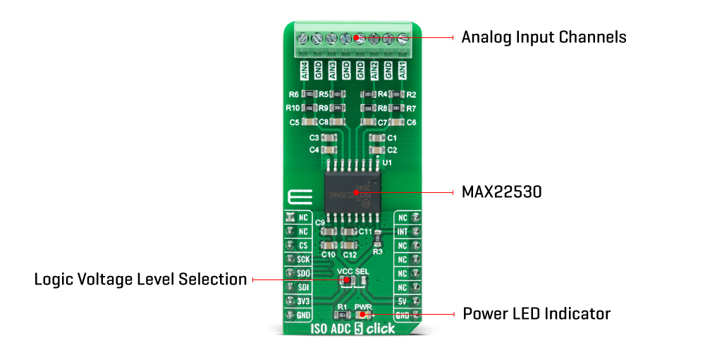
The ISO ADC 5 Click Board™ as its foundation uses the MAX22530, a 12-bit, 4-channel ADC with a 5kVRMS isolated SPI interface from Maxim Integrated. The ADC and all field-side circuits are powered by an integrated, isolated DC-DC converter that can verify field-side functionality even when there is no input signal or other field-side supply. It continually digitizes the input voltage on the field-side of an isolation barrier, and it transmits the data across the isolation barrier to the logic-side of the devices, where the magnitude of the input voltage is compared to programmable thresholds.
The MAX22530 ADC employs a 12-bit SAR architecture with a nominal sampling rate of 20ksps per channel and has an input voltage of up to 1.8V. Placed voltage dividers make the proper ADC input voltage on the input analog channels, which, based on the input in the range from 0 to 48V, gives the required input to the ADC in its range from 0 to 1.8V. After Power-Up, the ADC runs continually at the nominal sampling rate. The MAX22530 also features a precision internal voltage reference of 1.8V with a maximum error of ±2% over the entire operating temperature range.
The MAX22530 communicates with MCU using the standard SPI serial interface with a maximum frequency of 10MHz. Besides, it continuously monitors multiple possible fault conditions such as ADC functionality error, SPI framing error, CRC errors from SPI communications, and internal isolated data stream loss. This hardware alert feature is provided through the interrupt pin, routed on the CS pin of the mikroBUS™ socket, which asserts low when an enabled fault is detected.
The ISO ADC 5 Click Board™ can operate with both 3.3V and 5V logic voltage levels selected via the VCC SEL jumper. This way, it is allowed for both 3.3V and 5V capable MCUs to use the SPI communication lines properly. However, the Click board™ comes equipped with a library containing easy-to-use functions and an example code that can be used, as a reference, for further development.
SPECIFICATIONS
| Type | ADC |
| Applications | Can be used for high-density, multi-range, group-isolated, binary-input modules and provides a complete solution to any system requiring monitoring inputs without a separate isolated power supply |
| On-board modules | MAX22530 - 12-bit, 4-channel ADC with a 5kVRMS isolated SPI interface from Maxim Integrated |
| Key Features | Withstands 5kVRMS isolation for 60s, field-side self-powered with integrated DC-DC supply, 12-bit ADC with 20ksps per channel, flexible control and interface, and more |
| Interface | SPI |
| Compatibility | mikroBUS |
| Click board size | L (57.15 x 25.4 mm) |
| Input Voltage | 3.3V or 5V |
PINOUT DIAGRAM
This table shows how the pinout on ISO ADC 5 Click corresponds to the pinout on the mikroBUS™ socket (the latter shown in the two middle columns).
| Notes | Pin | Pin | Notes | ||||
|---|---|---|---|---|---|---|---|
| NC | 1 | AN | PWM | 16 | NC | ||
| NC | 2 | RST | INT | 15 | INT | Interrupt | |
| SPI Chip Select | CS | 3 | CS | RX | 14 | NC | |
| SPI Clock | SCK | 4 | SCK | TX | 13 | NC | |
| SPI Data OUT | SDO | 5 | MISO | SCL | 12 | NC | |
| SPI Data IN | SDI | 6 | MOSI | SDA | 11 | NC | |
| Power Supply | 3.3V | 7 | 3.3V | 5V | 10 | 5V | Power Supply |
| Ground | GND | 8 | GND | GND | 9 | GND | Ground |
ONBOARD SETTINGS AND INDICATORS
| Label | Name | Default | Description |
|---|---|---|---|
| LD1 | PWR | - | Power LED Indicator |
| JP1 | VCC SEL | Left | Logic Level Voltage Selection 3V3/5V: Left position 3V3, Right position 5V |
ISO ADC 5 CLICK ELECTRICAL SPECIFICATIONS
| Description | Min | Typ | Max | Unit |
|---|---|---|---|---|
| Supply Voltage VCC | 3.3 | - | 5 | V |
| Analog Channels Input Range | 0 | - | 48 | V |
| Maximum Withstanding-Isolation Voltage | - | - | 5 | KVrms |
| ADC Resolution | 12 | - | - | bits |
| Sample Rate | 18 | 20 | 22 | ksps |
| Operating Temperature Range | -40 | +25 | +125 | °C |
| General Information | |
|---|---|
Part Number (SKU) |
MIKROE-4758
|
Manufacturer |
|
| Physical and Mechanical | |
Weight |
0.02 kg
|
| Other | |
EAN |
8606027383465
|
Frequently Asked Questions
Have a Question?
Be the first to ask a question about this.