


Mikroelektronika d.o.o.
Analog MUX 3 Click Board™
Analog MUX 3 Click Board™
SKU: MIKROE-4580
Couldn't load pickup availability


Key Features
Overview
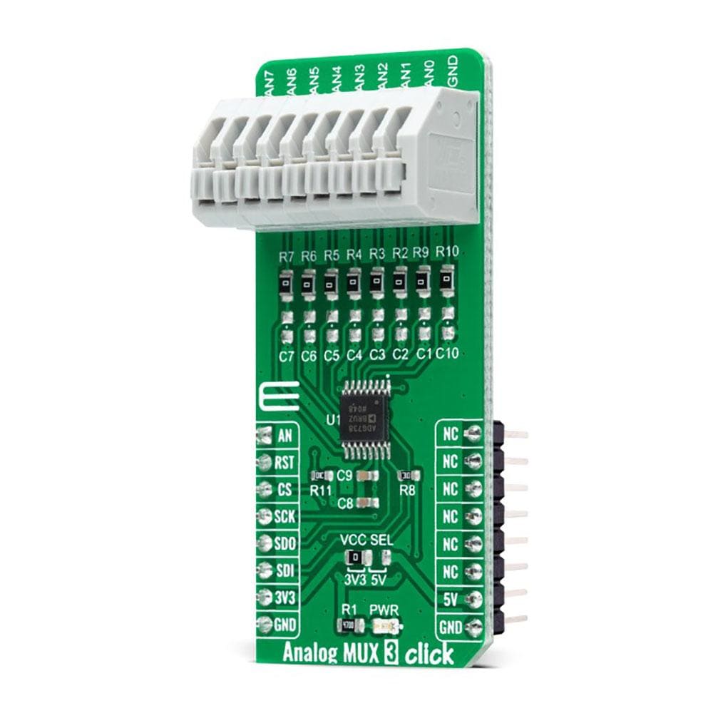
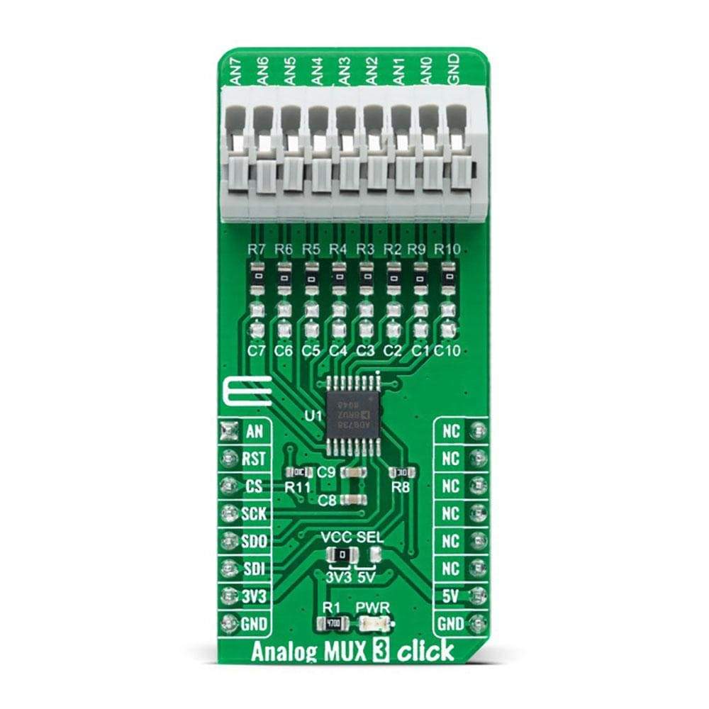
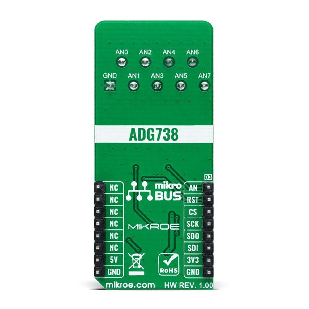
The Analog MUX 3 Click Board™ is a compact add-on board that switches one of the eight inputs to one output. This board features the ADG738, a CMOS analogue matrix switch with a serially-controlled SPI interface from Analog Devices. In an active state, the ADG738 conducts equally well in both directions, making it suitable for multiplexing and demultiplexing applications. It can also be configured as a type of switch array where any, all, or none of eight switches may be closed at any time. All channels exhibit ‘break-before-make switching action, preventing momentary shorting when switching channels. This Click Board™ is suitable for a wide range of applications, from industrial and instrumentation to medical, consumer, communications, and automotive systems.
The Analog MUX 3 Click is supported by a mikroSDK compliant library, which includes functions that simplify software development. This Click Board™ comes as a fully tested product, ready to be used on a system equipped with the mikroBUS™ socket.
Downloads
How Does The Analog MUX 3 Click Board™ Work?
The Analog MUX 3 Click Board™ uses the ADG738, a CMOS 8-channel analogue matrix switch with a serially-controlled SPI interface from Analog Devices. The ADG738 can operate equally well as either multiplexer, demultiplexer, or switch array, providing more flexibility. It also features a low on-resistance closely matched between switches and very flat over the entire signal range. During the Power-Up of the ADG738, all switching channels will be in the OFF condition, and the internal shift register will contain all zeros and remains so until a valid write takes place. All channels exhibit 'break-before-make switching action preventing momentary shorting when switching channels.

Each bit of the 8-bit serial word corresponds to one switch of the device. Internal switching channels are independently controlled by an individual bit, providing an option of having any, all, or none of the switches activated. All of the input channels of the multiplexer can be easily connected to a nine pole spring action block terminal, without having to use any additional tools, such as screwdrivers, while the output pin from the multiplexer is routed to the AN pin on the mikroBUS™ socket.
When changing the switch conditions, a new 8-bit word is written to the input shift register. Some of the bits may be the same as the previous write cycle, as the user may not wish to change the state of some switches. To minimize glitches on these switches' output, the ADG738 cleverly compares the state of switches from the previous write cycle. If the switch is already in the ON state and needs to stay in that condition, there will be minimal glitches on the switch's output.
The Analog MUX 3 Click Board™ communicates with MCU using the SPI serial interface compatible with standard SPI, QSPI™, MICROWIRE™, DSP interface standards, and operates at clock rates up to 30MHz. Also, this Click board™ has a Reset pin routed to the RST pin on the mikroBUS™ socket, which clears the input register and turns all switches to the OFF condition.
The Analog MUX 3 Click Board™ can operate with both 3.3V and 5V logic voltage levels selected via the VCC SEL jumper. This way, it is allowed for both 3.3V and 5V capable MCUs to properly use the SPI communication lines. However, the Click board™ comes equipped with a library containing easy-to-use functions and an example code that can be used, as a reference, for further development.
SPECIFICATIONS
| Type | Port expander |
| Applications | Can be used for a wide range of applications, from industrial and instrumentation to medical, consumer, communications, and automotive systems. |
| On-board modules | ADG738 - CMOS 8-channel analog matrix switch with a serially-controlled 3-wire SPI interface from Analog Devices |
| Key Features | 8-to-1 matrix switch, low on-resistance, 'Break-Before-Make' switching action, serially controlled, and more. |
| Interface | Analog,SPI |
| Compatibility | mikroBUS |
| Click board size | L (57.15 x 25.4 mm) |
| Input Voltage | 3.3V or 5V |
PINOUT DIAGRAM
This table shows how the pinout on the Analog MUX 3 Click Board™ corresponds to the pinout on the mikroBUS™ socket (the latter shown in the two middle columns).
| Notes | Pin | Pin | Notes | ||||
|---|---|---|---|---|---|---|---|
| Analog Signal | AN | 1 | AN | PWM | 16 | NC | |
| Reset | RST | 2 | RST | INT | 15 | NC | |
| SPI Chip Select | CS | 3 | CS | RX | 14 | NC | |
| SPI Clock | SCK | 4 | SCK | TX | 13 | NC | |
| SPI Data OUT | SDO | 5 | MISO | SCL | 12 | NC | |
| SPI Data IN | SDI | 6 | MOSI | SDA | 11 | NC | |
| Power Supply | 3.3V | 7 | 3.3V | 5V | 10 | 5V | Power Supply |
| Ground | GND | 8 | GND | GND | 9 | GND | Ground |
ONBOARD SETTINGS AND INDICATORS
| Label | Name | Default | Description |
|---|---|---|---|
| LD1 | PWR | - | Power LED Indicator |
| JP1 | VCC SEL | Left | Logic Level Voltage Selection 3V3/5V: Left position 3V3, Right position 5V |
ANALOG MUX 3 CLICK ELECTRICAL SPECIFICATIONS
| Description | Min | Typ | Max | Unit |
|---|---|---|---|---|
| Supply Voltage | 3.3 | - | 5 | V |
| Analog Input Signal Range | 0 | - | 5 | V |
| On-Resistance | - | - | 4.5 | Ω |
| Operating Temperature Range | -40 | +25 | +105 | °C |
| General Information | |
|---|---|
Part Number (SKU) |
MIKROE-4580
|
Manufacturer |
|
| Physical and Mechanical | |
Weight |
0.023 kg
|
| Other | |
EAN |
8606027382260
|
Frequently Asked Questions
Have a Question?
Be the first to ask a question about this.