


Mikroelektronika d.o.o.
DTMF Decoder Click Board™
DTMF Decoder Click Board™
SKU: MIKROE-4579
Couldn't load pickup availability
Overview
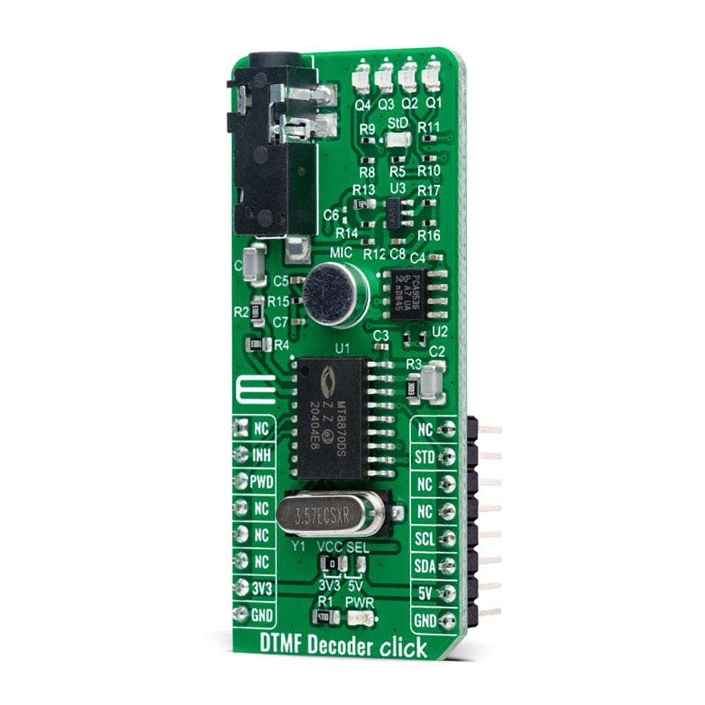
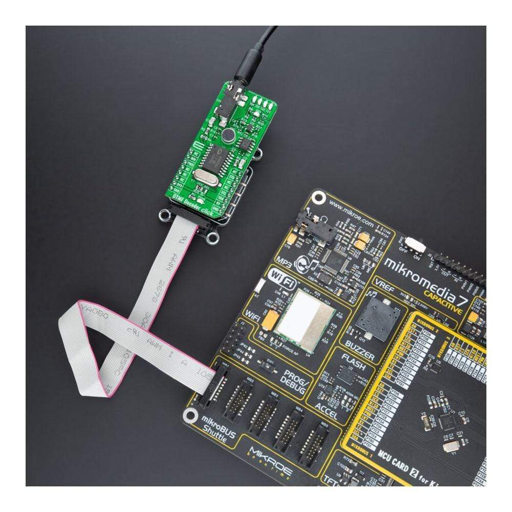
The DTMF Decoder Click Board™ is a compact add-on board that contains an integrated DTMF receiver with enhanced sensitivity. This board features the MT8870D, a complete DTMF receiver integrating the band-split filter and digital decoder functions from Microchip Technology. It offers low power consumption and high performance and uses digital counting techniques to detect and decode all 16 DTMF tone-pairs into a 4-bit code. Whenever a valid tone is detected, it outputs the associated value in binary on four LEDs, with an additional indicator that strobes after each new tone. This Click Board™ is suitable for paging systems, remote control, electronic communications circuits, and various other applications.
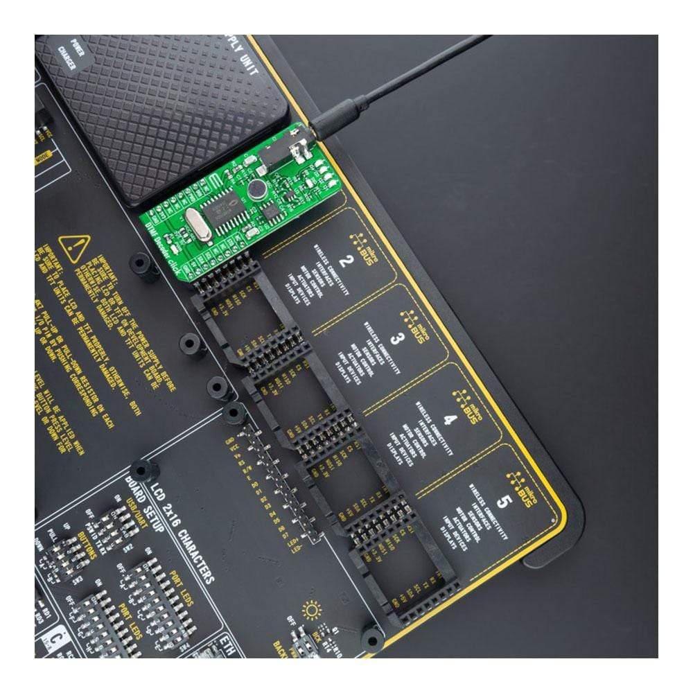
The DTMF Decoder Click Board™ is supported by a mikroSDK compliant library, which includes functions that simplify software development. This Click Board™ comes as a fully tested product, ready to be used on a system equipped with the mikroBUS™ socket.
Downloads
How Does The DTMF Decoder Click Board™ Work?
The DTMF Decoder Click Board™ is based on the MT8870D, an integrated DTMF receiver with enhanced sensitivity from Microchip Technology. It offers low power consumption and high performance and consists of a band split filter section, which separates the high and low group tones, followed by a digital counting section that verifies the received tones' frequency and duration before passing the corresponding code to the output bus.
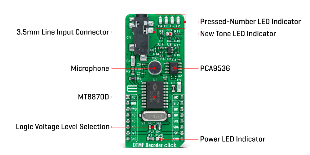
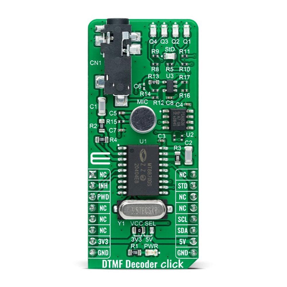
The DTMF Decoder Click Board™ has two ways to detect tones: with a mobile phone with a 3.5mm jack which provides the DTMF signals to MT8870D decoder, or using an onboard microphone used to listen the DTMF tones generated by the cell phone. The MT8870D uses digital counting techniques to detect and decode all 16 DTMF tone-pairs into a 4-bit code.
The DTMF Decoder Click Board™ communicates with MCU using standard I2C 2-Wire interface, with a clock frequency up to 100kHz in the Standard and 400kHz in the Fast Mode. Using the PCA9536 port expander that communicates with the MCU via I2C communication, it is possible to visually display, in binary form, the digit of the pressed number. The digit in binary form is then visually displayed using four red LEDs, labelled from Q1 to Q4, located in the board's upper right corner.
The DTMF Decoder Click Board™ also has a power-down feature routed on the CS pin of the mikroBUS™ socket labelled as PWD. A logic high applied to pin PWD will power down the device to minimize the power consumption in a Standby mode, which stops the oscillator and the filters' functions. Also, it uses the interrupt pin of the mikroBUS™ labelled as STD with an additional LED indicator signaling that a received tone pair has been registered, and INH pin, which inhibits the detection of tones representing characters A, B, C, and D. The output code will remain the same as the previously detected code.
The DTMF Decoder Click Board™can operate with both 3.3V and 5V logic voltage levels selected via the VCC SEL jumper. This way, it is allowed for both 3.3V and 5V capable MCUs to properly use the I2C communication lines. However, the Click board™ comes equipped with a library containing easy-to-use functions and an example code that can be used, as a reference, for further development.
SPECIFICATIONS
| Type | Signal Processing |
| Applications | Can be used for paging systems, remote control, electronic communications circuits, and various other applications. |
| On-board modules | MT8870D - an integrated DTMF receiver with enhanced sensitivity from Microchip Technology |
| Key Features | Low power consumption, complete DTMF receiver, high performance, internal gain setting amplifier, power-down mode, inhibit mode, and more. |
| Interface | I2C |
| Compatibility | mikroBUS |
| Click board size | L (57.15 x 25.4 mm) |
| Input Voltage | 3.3V or 5V |
PINOUT DIAGRAM
This table shows how the pinout of the DTMF Decoder Click Board™ corresponds to the pinout on the mikroBUS™ socket (the latter shown in the two middle columns).
| Notes | Pin | Pin | Notes | ||||
|---|---|---|---|---|---|---|---|
| NC | 1 | AN | PWM | 16 | NC | ||
| Inhibit Mode | INH | 2 | RST | INT | 15 | STD | New Tone Indicator |
| Power Down Mode | PWD | 3 | CS | RX | 14 | NC | |
| NC | 4 | SCK | TX | 13 | NC | ||
| NC | 5 | MISO | SCL | 12 | SCL | I2C Clock | |
| NC | 6 | MOSI | SDA | 11 | SDA | I2C Data | |
| Power Supply | 3.3V | 7 | 3.3V | 5V | 10 | 5V | Power Supply |
| Ground | GND | 8 | GND | GND | 9 | GND | Ground |
ONBOARD SETTINGS AND INDICATORS
| Label | Name | Default | Description |
|---|---|---|---|
| LD1 | PWR | - | Power LED Indicator |
| LD2 | StD | - | New Tone LED Indicator |
| LD3-LD6 | Q1 - Q4 | - | Pressed-Number LED Indicator |
| JP1 | VCC SEL | Left | Logic Level Voltage Selection 3V3/5V: Left position 3V3, Right position 5V |
DTMF DECODER CLICK ELECTRICAL SPECIFICATIONS
| Description | Min | Typ | Max | Unit |
|---|---|---|---|---|
| Supply Voltage | 3.3 | - | 5 | V |
| Frequency | - | 3.579545 | - | MHz |
| Power Consumption | - | 15 | - | mW |
| Operating Temperature Range | -40 | +25 | +85 | °C |
| General Information | |
|---|---|
Part Number (SKU) |
MIKROE-4579
|
Manufacturer |
|
| Physical and Mechanical | |
Weight |
0.021 kg
|
| Other | |
EAN |
8606027382291
|
Frequently Asked Questions
Have a Question?
Be the first to ask a question about this.