


Mikroelektronika d.o.o.
CAN FD 6 Click Board™
CAN FD 6 Click Board™
SKU: MIKROE-4572
Couldn't load pickup availability
Key Features
Overview
Enhance your automotive and industrial applications with the CAN FD 6 Click Board™. This compact add-on board integrates a high-performance CAN transceiver supporting Controller Area Network (CAN) and Controller Area Network Flexible Data-Rate (CAN FD) protocols. Developed with the TCAN4550 CAN FD controller from Texas Instruments, this board enables data rates of up to 5 megabits per second (Mbps).
The CAN FD 6 Click Board™ offers high-bandwidth capabilities and data-rate flexibility, bridging the gap between the CAN bus and the system processor seamlessly through an SPI interface. It not only supports classical CAN and CAN FD but also features wake-up functionality, allowing for local and bus wake using the CAN bus.
- High-speed CAN networking made easy for automotive and industrial settings.
- Low-power mode with wake-up capabilities via the CAN bus ensures efficient energy consumption.
This Click Board™ is the perfect solution for applications where reliable high-speed communication is essential combined with a need for power efficiency. Additionally, the board is supported by a mikroSDK compliant library, providing developers with simplified software development functions.
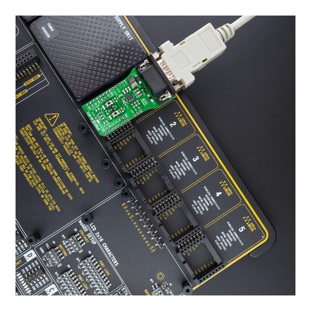
Tested thoroughly to ensure reliability, the CAN FD 6 Click Board™ is ready to be integrated into systems equipped with a mikroBUS™ socket. Experience seamless data transfer and efficient power management with this advanced add-on board.
Downloads
How Does The CAN FD 6 Click Board™ Work?
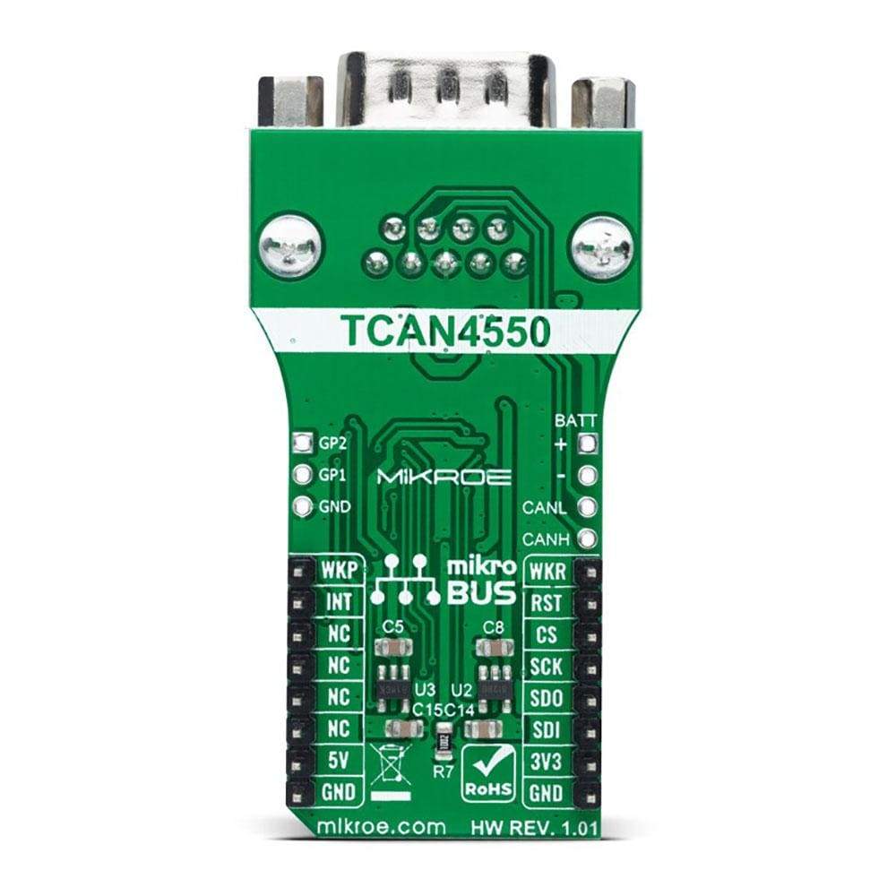
The CAN FD 6 Click Board™ is based on the TCAN4550, a CAN transceiver that supports CAN and CAN FD protocols and provides an interface between the CAN bus and the CAN protocol controller up to 5 megabits per second (Mbps) from Texas Instruments. It is characterized by high-bandwidth and data-rate flexibility, provides an SPI interface between the CAN bus and the system processor, and supports wake-up features local and bus wake using the CAN bus. The device includes many protection features providing CAN bus robustness, including fail-safe mode, internal dominant state timeout, and wide bus operating range.

![]()
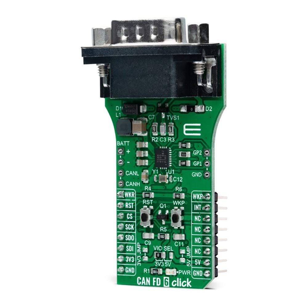
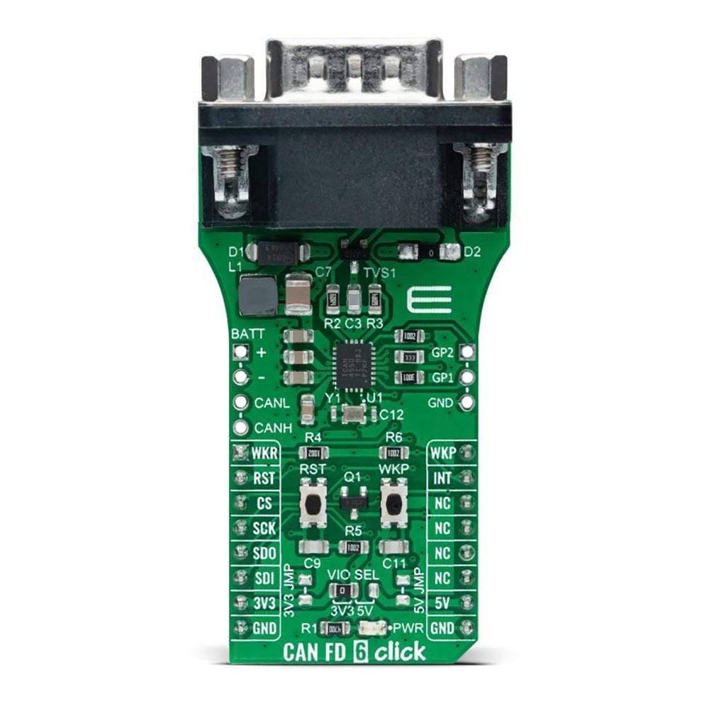
The TCAN4550 has one pin used for waking up the device from Sleep mode. This pin is connected to an external button labelled as WAKE and the PWM pin of the mikroBUS™ socket labelled as WKP to generate a local Wake-Up function. A Wake-Up event on the CAN bus switches the inhibit output pin INH to the high level. The INH pin provides an internal switch towards the battery supply voltage and control external voltage regulators, the MCP1804 from Microchip. Through SMD jumpers labelled as 3V3JMP and 5VJMP, the LDOs output voltages can be used to power up the mikroBUS™ 3.3V and 5V power rails. However, it should be noted that MikroE does not advise powering up their systems this way. That is why these jumpers are left unpopulated by default.
CAN FD 6 Click communicates with MCU using a standard SPI interface supporting clock rates up to 18MHz to transmit and reception CAN frames. With an additional 40MHz crystal, the TCAN4550 can meet CAN FD rates up to 5 Mbps data rates to support higher data throughput and operates from a 6V to 24V external power supply header on the board's right side. This feature makes the TCAN4550 device ideal for many different applications, including those in the automotive market.
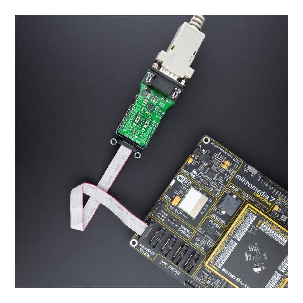
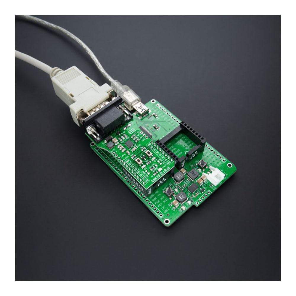
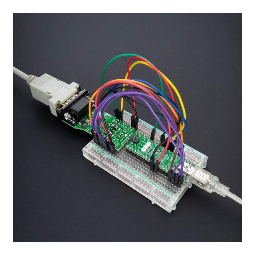
The CAN FD 6 Click Board™ comes equipped with the industry-standard DB-9 connector, making interfacing with the CAN bus simple and easy. Besides, the user can connect the CAN signals directly through the CAN External header located on the board's left edge.
In addition to these features, the TCAN4550 also uses several GPIO pins connected to the mikroBUS™ socket. The RST pin the mikroBUS™ can perform the Hardware Reset function, which resets the device to the default settings and puts it into standby mode. This feature can also be achieved through the onboard push-button labelled as RST. Next to these pins, the ATA6571 uses the WKR pin as a dedicated wake-up request pin from a bus wake request and INT pin as an interrupt feature routed on the AN and INT pin of the mikroBUS™ socket. For interrupt purposes, the user can also use GPIO pins from the header positioned on the board's right side.
The CAN FD 6 Click Board™ can operate with both 3.3V and 5V logic voltage levels selected via the VIO SEL jumper. It allows for both 3.3V and 5V capable MCUs to use the UART communication lines properly. However, the Click board™ comes equipped with a library containing easy-to-use functions and an example code that can be used, as a reference, for further development.
SPECIFICATIONS
| Type | CAN |
| Applications | Can be used for high-speed CAN networks in automotive and industrial applications, especially where low-power mode with wake-up capability via the CAN bus is required. |
| On-board modules | TCAN4550 - CAN FD controller that provides an interface between the CAN bus and the CAN protocol controller up to 5Mbps from Texas Instruments |
| Key Features | Low power consumption, classic CAN backwards compatible, wide operating range, optimized behaviour when unpowered, high-bandwidth, data-rate flexibility, and more. |
| Interface | SPI |
| Compatibility | mikroBUS |
| Click board size | L (57.15 x 25.4 mm) |
| Input Voltage | 3.3V or 5V, External |
PINOUT DIAGRAM
This table shows how the pinout of the CAN FD 6 Click Board™ corresponds to the pinout on the mikroBUS™ socket (the latter shown in the two middle columns).
| Notes | Pin |
|
Pin | Notes | |||
|---|---|---|---|---|---|---|---|
| Wake Request | WKR | 1 | AN | PWM | 16 | WKP | Wake Up |
| Reset | RST | 2 | RST | INT | 15 | INT | Interrupt |
| SPI Chip Select | CS | 3 | CS | RX | 14 | NC | |
| SPI Clock | SCK | 4 | SCK | TX | 13 | NC | |
| SPI Data OUT | SDO | 5 | MISO | SCL | 12 | NC | |
| SPI Data IN | SDI | 6 | MOSI | SDA | 11 | NC | |
| Power Supply | 3.3V | 7 | 3.3V | 5V | 10 | 5V | Power Supply |
| Ground | GND | 8 | GND | GND | 9 | GND | Ground |
ONBOARD SETTINGS AND INDICATORS
| Label | Name | Default | Description |
|---|---|---|---|
| LD1 | PWR | - | Power LED Indicator |
| JP1 | VIO SEL | Left | Logic Level Voltage Selection 3V3/5V: Left position 3V3, Right position 5V |
| JMPR1 | PWR | Unpopulated | 3V3/5V LDO Jumpers |
| JMPR2 | PWR | Unpopulated | 3V3/5V LDO Jumpers |
| J1 | BATT | Unpopulated | External Power Supply Header |
| J2 | GP | Unpopulated | Configurable GPIO Header |
| J3 | CAN | Unpopulated | External CANH/CANL Lines Header |
CAN FD 6 CLICK ELECTRICAL SPECIFICATIONS
| Description | Min | Typ | Max | Unit |
|---|---|---|---|---|
| Supply Voltage VIO | 3.3 | - | 5 | V |
| External Supply Voltage BATT | 6 | - | 24 | V |
| Data Rate | - | - | 5 | Mbps |
| Operating Temperature Range | -40 | +25 | +125 | °C |
| General Information | |
|---|---|
Part Number (SKU) |
MIKROE-4572
|
Manufacturer |
|
| Physical and Mechanical | |
Weight |
0.02 kg
|
| Other | |
EAN |
5055383601196
|
Frequently Asked Questions
Have a Question?
Be the first to ask a question about this.