


Mikroelektronika d.o.o.
Load Cell 4 Click Board™
Load Cell 4 Click Board™
SKU: MIKROE-4458
Couldn't load pickup availability

Overview
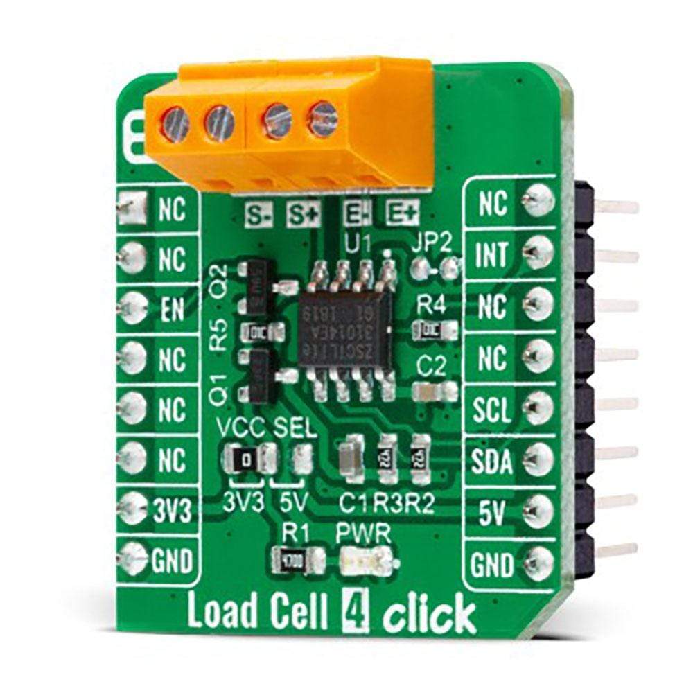
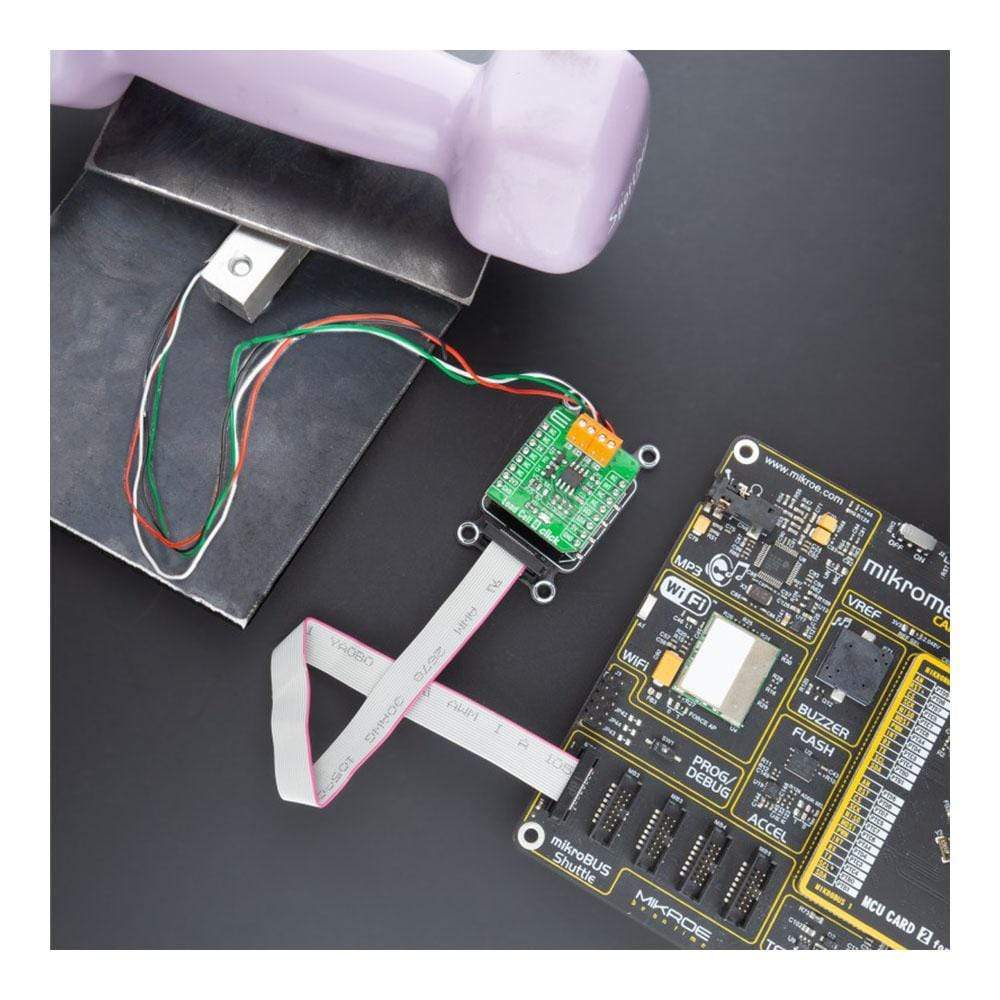
The Load Cell 4 Click Board™ is a compact add-on board that contains a resistive sensor signal conditioner with a fast power-up data output response. This board features the ZSC31014, a CMOS integrated circuit for highly accurate amplification and analogue-to-digital conversion of differential and half-bridge input signals from Renesas. This Click Board™ is well suited for sensor-specific correction of bridge sensors and adjustable to nearly all piezo-resistive bridge sensors. Digital compensation of signal offset, sensitivity, temperature drift, and non-linearity is accomplished via an internal signal processor running a correction algorithm with calibration coefficients stored in a non-volatile EEPROM.
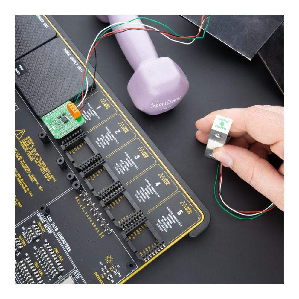
The Load Cell 4 Click Board™ has many features that make it a perfect solution for safety-critical and weight measurement applications
Downloads
How Does The Load Cell 4 Click Board™ Work?
The Load Cell 4 Click Board™ is based on the ZSC31014, a CMOS integrated circuit for highly accurate amplification and analog-to-digital conversion of differential and half-bridge input signals from Renesas. The ZSC31014 has a fully differential chopper-stabilized preamplifier with 8 programmable gain settings (1.5, 3, 6, 12, 24, 48, 96, and 192) through a 14-bit ADC. The resolution of the output depends on the input span and the analog gain setting. The system clock of the ZSC31014 can operate at 1MHz (lower power, better noise performance) or at 4MHz (faster sample rates). Internal DSP core uses coefficients stored in EEPROM to precisely calibrate/condition the amplified differential input signal. Temperature can be measured from an internal temperature sensor, which can be calibrated to compensate for the temperature effects of the sensor bridge.
.jpg)
After the Power-On Reset function, the ZSC31014 wakes, and if it receives the Start_CM command during the command window, it goes into Command Mode. This Mode is primarily used in the calibration environment, and during Command Mode, the device executes commands sent by the I2C master. The ZSC31014 remains in Command Mode until it receives the Start_NOM command, which starts the Normal Operation Mode. Operation after the Power-On sequence depends on whether the part is programmed in Sleep Mode or Update Mode. In Sleep Mode, the ZSC31014 waits for commands from the master before taking measurements, while in Update Mode, data is taken at a fixed, selectable rate.
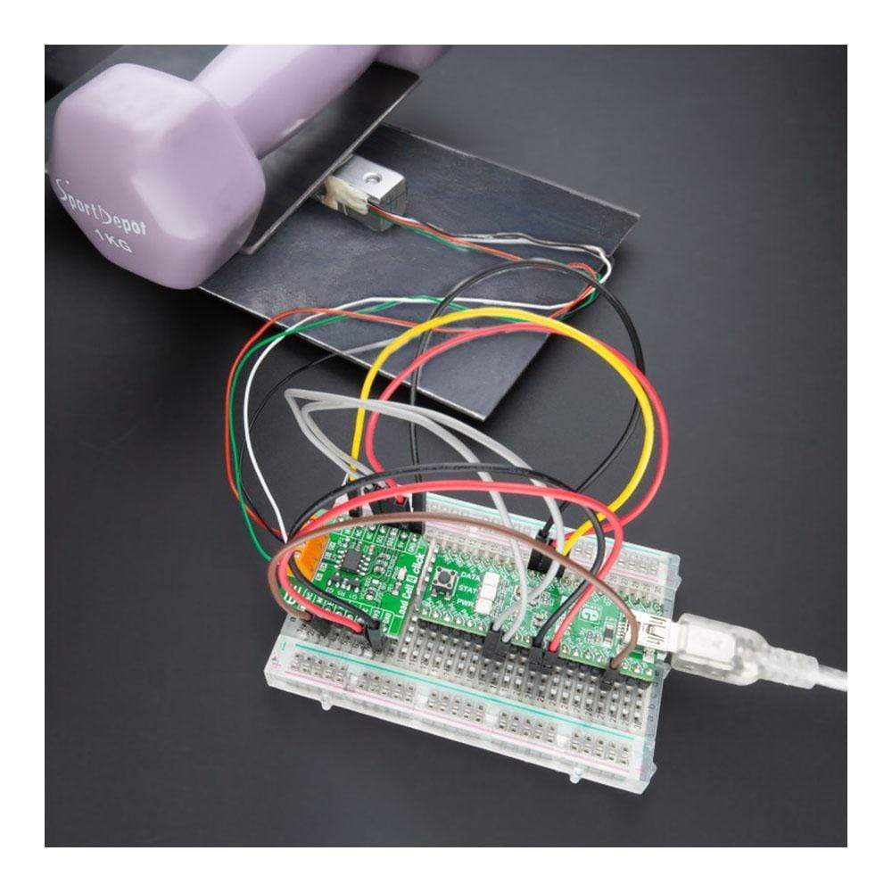
The Load Cell 4 Click Board™ communicates with MCU using the standard I2C 2-Wire interface with a clock frequency from 100 up to 400 kHz. The INT pin of the mikroBUS™ socket, used as an interrupt, rises when new output data is ready and falls when the next I2C communication occurs. It is most useful if the part is configured in Sleep Mode to indicate to the system that a new conversion is ready. Besides, this Click board™ also possesses an Enable pin labeled as EN, routed to the CS pin of the mikroBUS™ socket, which serves to turn the ZSC31014's power supply on/off.
The Load Cell 4 Click Board™ is designed to operate with both 3.3V and 5V logic voltage levels selected via the VCC SEL jumper. It allows for both 3.3V and 5V capable MCUs to use the I2C communication lines properly. However, the Click board™ comes equipped with a library that contains functions and an example code that can be used, as a reference, for further development.
Specifications
| Type | Force |
| Applications | Can be used for safety-critical and weight measurement applications. |
| On-board modules | The Load Cell 4 Click Board™ is based on the ZSC31014, a CMOS integrated circuit for highly accurate amplification and analog-to-digital conversion of differential and half-bridge input signals from Renesas. |
| Key Features | High accuracy, digital compensation of sensor offset, sensitivity,temperature drift, and non-linearity, eight programmable analog gain settings, internal temperature compensation for sensor correction and for corrected temperature output, and more. |
| Interface | I2C |
| Compatibility | mikroBUS |
| Click board size | S (28.6 x 25.4 mm) |
| Input Voltage | 3.3V or 5V |
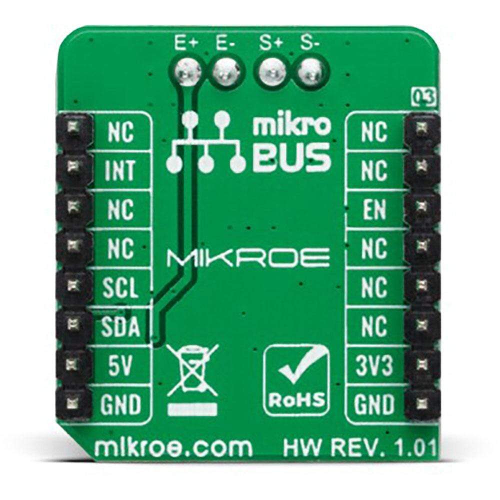
Pinout diagram
This table shows how the pinout on the Load Cell 4 Click Board™ corresponds to the pinout on the mikroBUS™ socket (the latter shown in the two middle columns).
| Notes | Pin | Pin | Notes | ||||
|---|---|---|---|---|---|---|---|
| NC | 1 | AN | PWM | 16 | NC | ||
| NC | 2 | RST | INT | 15 | INT | Interrupt | |
| Enable | EN | 3 | CS | RX | 14 | NC | |
| NC | 4 | SCK | TX | 13 | NC | ||
| NC | 5 | MISO | SCL | 12 | SCL | I2C Clock | |
| NC | 6 | MOSI | SDA | 11 | SDA | I2C Data | |
| Power Supply | 3.3V | 7 | 3.3V | 5V | 10 | 5V | Power Supply |
| Ground | GND | 8 | GND | GND | 9 | GND | Ground |
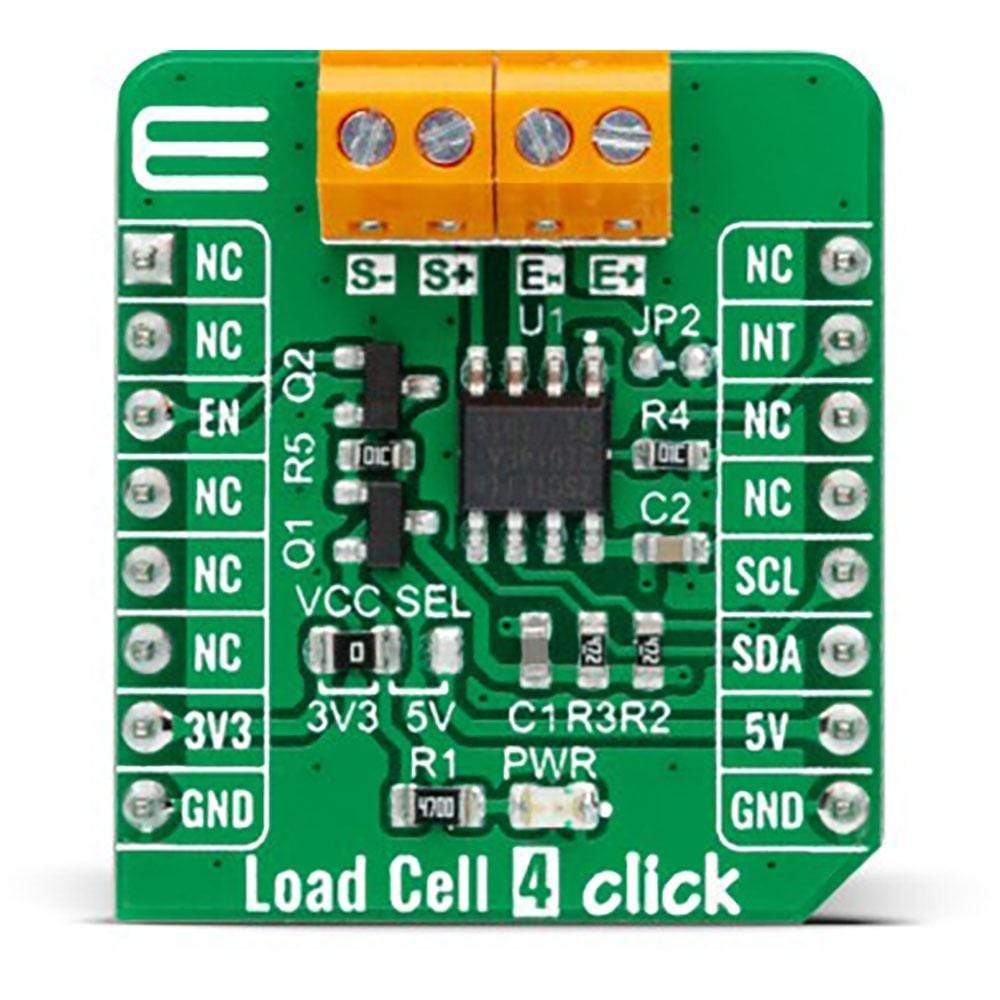
Onboard settings and indicators
| Label | Name | Default | Description |
|---|---|---|---|
| LD1 | PWR | - | Power LED Indicator |
| JP1 | VCC SEL | Left | Logic Level Voltage Selection 3V3/5V: Left position 3V3, Right position 5V |
| JP2 | - | Unpopulated | Bridge Sink Ground Selection |
Load Cell 4 Click electrical specifications
| Description | Min | Typ | Max | Unit |
|---|---|---|---|---|
| Supply Voltage | 2.7 | - | 5.5 | V |
| Resolution | - | 14 | - | bits |
| Operating Temperature Range | -40 | - | +125 | °C |
| General Information | |
|---|---|
Part Number (SKU) |
MIKROE-4458
|
Manufacturer |
|
| Physical and Mechanical | |
Weight |
0.017 kg
|
| Other | |
EAN |
8606027381607
|
Frequently Asked Questions
Have a Question?
Be the first to ask a question about this.