

Mikroelektronika d.o.o.
RF Switch Click Board™
RF Switch Click Board™
SKU: MIKROE-4168
Couldn't load pickup availability


Overview
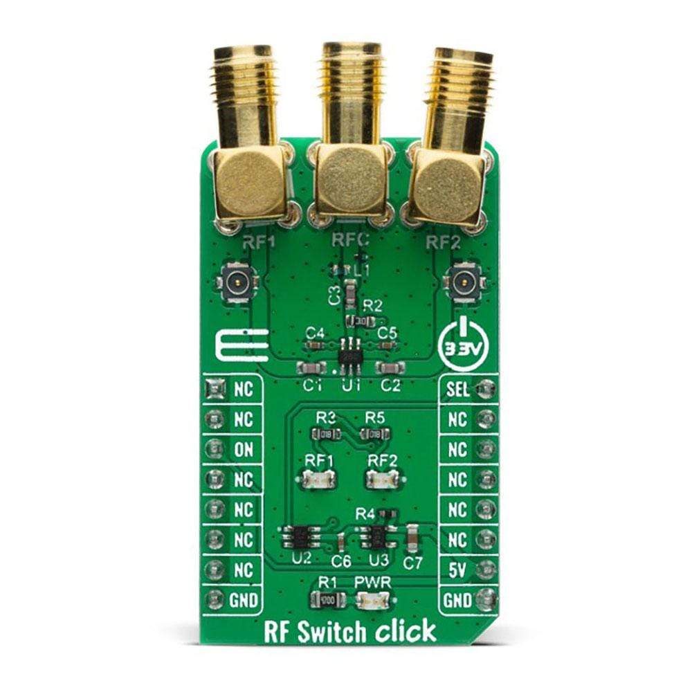
The RF Switch Click Board™ is equipped with the MASWSS0115, a GaAs PHEMT MMIC single-pole, double-throw (SPDT) switch developed by Macom for switching between small signal components such as filter banks, single-band LNAs, converters, etc. The MASWSS0115 is ideally suited for applications where very small size and low cost are required.
The RF Switch Click Board™ can be used for low power, low loss requirements in all systems operating up to 3 GHz, including PCS, GSM, DCS, Bluetooth, and other receive chain applications. The Click Board™ board includes additional drivers in the form of a complementary control and power switch for safe switching operations. RF Switch Click Board™ provides easy signal switching with an insertion loss of 0.3 dB at 2.4 GHz and maximum power consumption of 20µA.
Downloads
How Does The RF Switch Click Board™Work?
The RF Switch Click Board™ features MASWSS0115, a GaAs PHEMT MMIC single-pole, double-throw (SPDT) switch in a low cost, lead-free SC-70 (SOT-363) surface mount plastic package. The MASWSS0115 is ideally suited for applications where a very small size and low cost are required. Typical applications are dual-band systems that require switching between small signal components such as filter banks, single-band LNAs, converters, etc. This part can be used for low power, low loss requirements in all systems operating up to 3 GHz, including PCS, GSM, DCS, Bluetooth, and other receive chain applications. The MASWSS0115 is fabricated using a 0.5 micron gate length GaAs PHEMT process. The process features full passivation for performance and reliability.
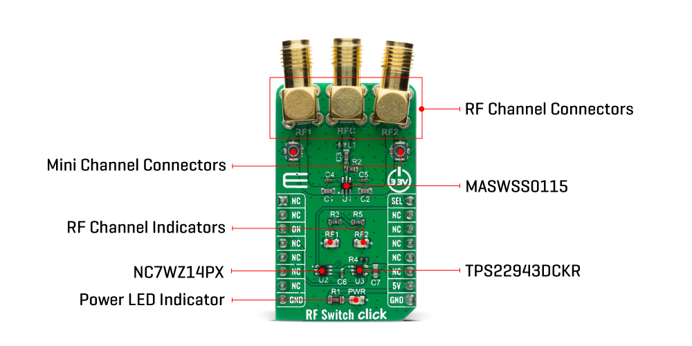
Featured chip MASWSS0115 provides signal switching of 50MHz to up to 3GHz with an insertion loss of 0.3 dB at 2.4 GHz and power consumption of 5 µA at +2.3V. Ultra High-Speed CMOS inverter labelled as NC7WZ14 is used for driving and controlling an RF switch with the typical switching time of 3,2 ns. Additionally, a load switch TPS22943DCKR can enable or disable the RF switch by electrically detaching the power supply. RF Switch Click Board™ uses the 5V to supply the switch driver while 3.3V microcontroller can be used to communicate with the control circuitry.
Two LEDs (RF1 and RF2) indicate the current active RF port as a visual representation of a state of the switch. Since RF1 is complementary to RF2, the switching can be achieved with only one GPIO pin. The RFC is an input of the switch with the possibility of redirecting the RF signal to RF1 or RF2 port. Besides switching SEL pin, the pin labelled as ON is used for power control. All of the switch ports are accessible on the connectors located on top of the Click Board™ with the addition of miniature coaxial connectors for both RF ports.
SPECIFICATIONS
| Type | Port expander |
| Applications | Typical applications include the systems where an RF signal has multiple possible paths like cellular infrastructure, wireless devices, automotive telematics, mobile radio, test equipment. |
| On-board modules | The RF Switch Click Board™ uses the MASWSS0115 IC, a GaAs PHEMT MMIC single-pole, double-throw (SPDT) switch , from Macom. |
| Key Features | GaAs single pole, double throw (SPDT) switch in a low cost and very small size package |
| Interface | GPIO |
| Compatibility | mikroBUS |
| Click board size | M (42.9 x 25.4 mm) |
| Input Voltage | 5V |
PINOUT DIAGRAM
This table shows how the pinout of the RF Switch Click Board™ corresponds to the pinout on the mikroBUS™ socket (the latter shown in the two middle columns).
| Notes | Pin | Pin | Notes | ||||
|---|---|---|---|---|---|---|---|
| NC | 1 | AN | PWM | 16 | SEL | Port Select | |
| NC | 2 | RST | INT | 15 | NC | ||
| Power On | ON | 3 | CS | RX | 14 | NC | |
| NC | 4 | SCK | TX | 13 | NC | ||
| NC | 5 | MISO | SCL | 12 | NC | ||
| NC | 6 | MOSI | SDA | 11 | NC | ||
| NC | 7 | 3.3V | 5V | 10 | 5V | Power Supply | |
| Ground | GND | 8 | GND | GND | 9 | GND | Ground |
ONBOARD SETTINGS AND INDICATORS
| Label | Name | Default | Description |
|---|---|---|---|
| LD1 | PWR | - | Power LED Indicator |
| LD2 | RF1 | - | RF Channel Indicator 1 |
| LD3 | RF2 | - | RF Channel Indicator 2 |
| General Information | |
|---|---|
Part Number (SKU) |
MIKROE-4168
|
Manufacturer |
|
| Physical and Mechanical | |
Weight |
0.026 kg
|
| Other | |
EAN |
8606018717880
|
Frequently Asked Questions
Have a Question?
Be the first to ask a question about this.