


Mikroelektronika d.o.o.
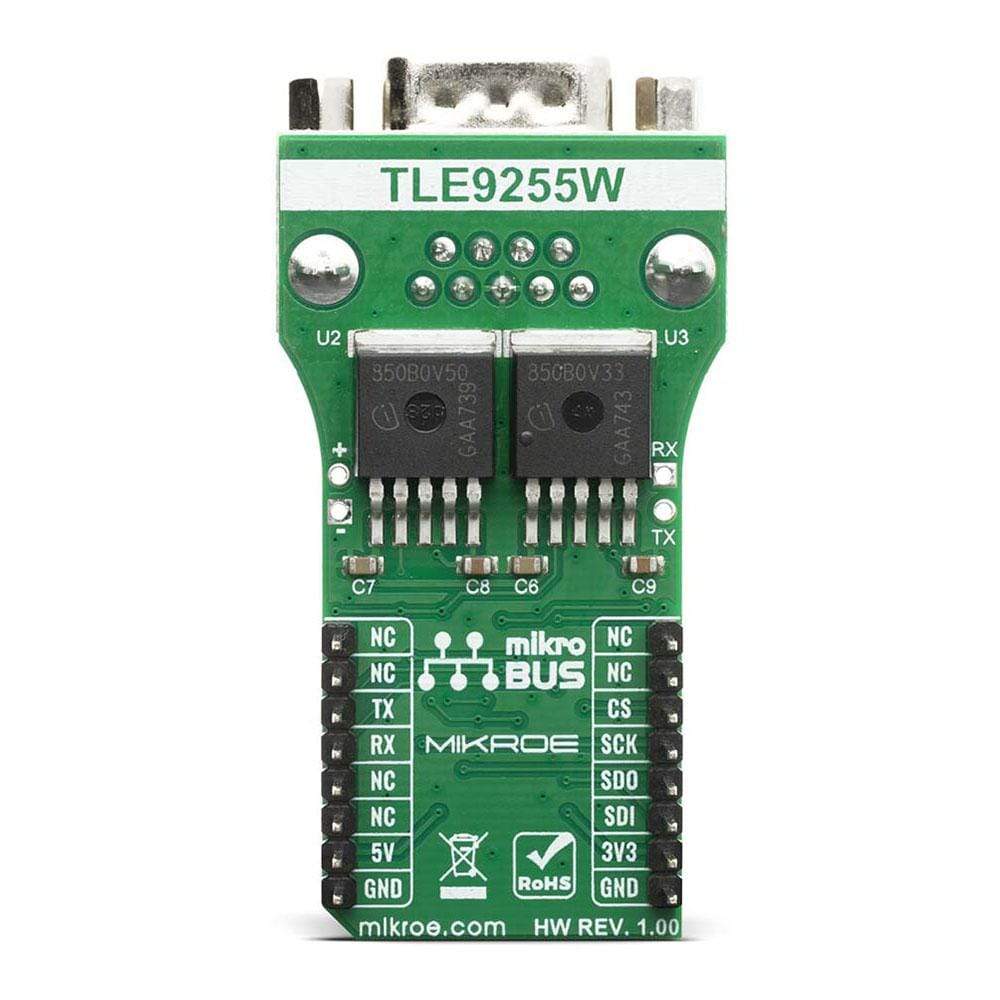
CAN FD 2 Click Board™
CAN FD 2 Click Board™
SKU: MIKROE-4062
Couldn't load pickup availability


Overview
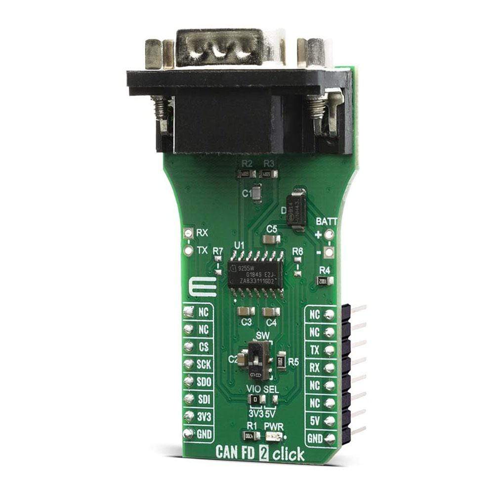
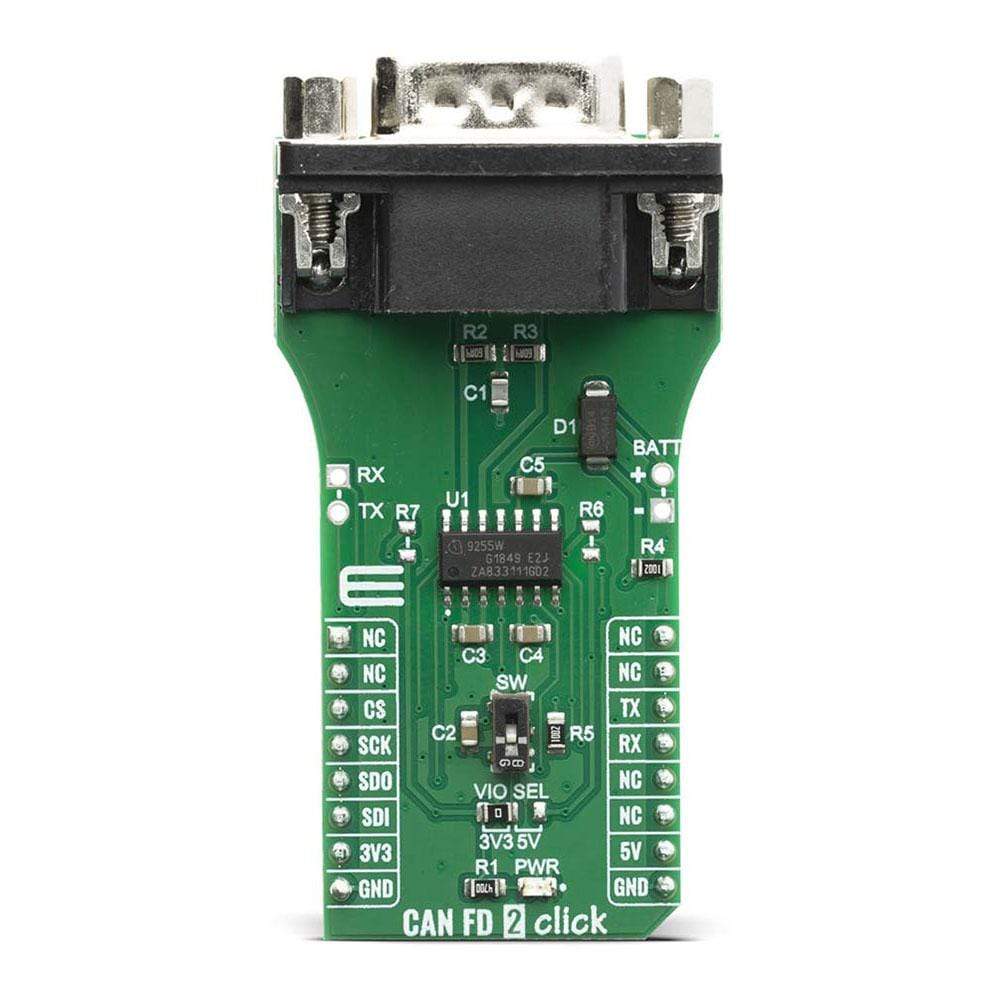
The CAN FD 2 Click Board™ is an HS CAN transceiver add on board, suitable for the evaluation of the TLE9255W CAN network transceiver from Infineon. The transceiver itself drives the signals to the CAN bus and protects the microcontroller from interference generated within the CAN network. Based on the high symmetry of the CANH and CANL signals, the TLE9255W provides a very low level of electromagnetic emission within a wide frequency range, allowing the operation of the TLE9255W without a common mode choke in automotive and industrial applications.
Downloads
How Does The CAN 2 FD Click Board™ Work?
The CAN 2 FD Click Board™ features TLE9255W a CAN protocol controller a part of the Infineon standard HS CAN transceiver family and provides beside CAN partial networking functions also a CAN FD capability up to 5 MBit/s in HS CAN networks. Configured as a partial networking HS CAN transceiver the TLE9255W can drive and receive CAN FD messages. It can also be used to block the payload of CAN FD messages. This CAN FD tolerant feature allows the usage of microcontrollers in CAN FD networks, which are not CAN FD capable. The two non-low power modes (Normal-operating Mode and Receive-only Mode) and the two low power modes (Sleep Mode and Stand-by Mode) provide minimum current consumption based on the required functionality.

The SPI of TLE9255W controls the setup of the wake-up messages and the status message generated by the internal state machine. Most of the functions, including wake-up functions, INH output control, mode control, undervoltage control are configurable by the SPI. This allows a very flexible usage of the TLE9255W in different applications.
High speed CAN (HS CAN) is a serial bus system that connects microcontrollers, sensors and actuators for realtime control applications. ISO 11898-2 (2016) describes the use of the Controller Area Network (CAN) within road vehicles. According to the 7-layer OSI reference model the physical layer of a HS CAN bus system specifies the data transmission from one CAN node to all other available CAN nodes within the network. The CAN transceiver is part of the physical layer.
The HS CAN transceiver TLE9255W includes a receiver and a transmitter unit, allowing the transceiver to send data to the bus medium and monitoring the data from the bus medium at the same time. It converts the serial data stream, which is available on the transmit data input TxD, to a differential output signal on the CAN bus, provided by the CANH and CANL pins. The receiver stage of the TLE9255W monitors the data on the CAN bus and converts it to a serial, single-ended signal on the RxD output pin.
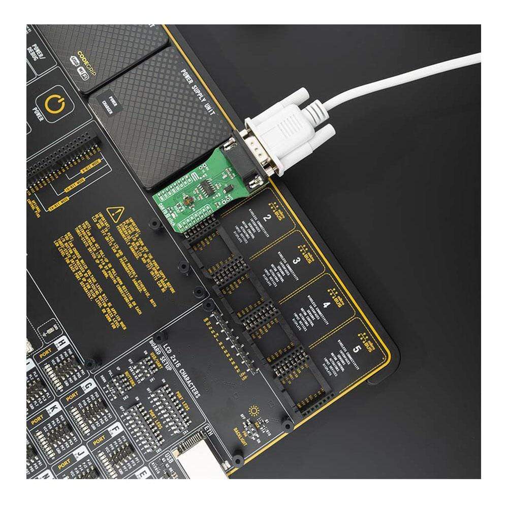
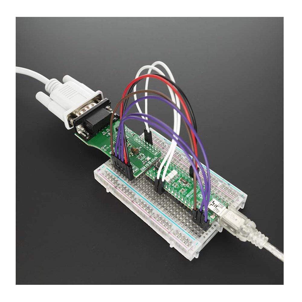
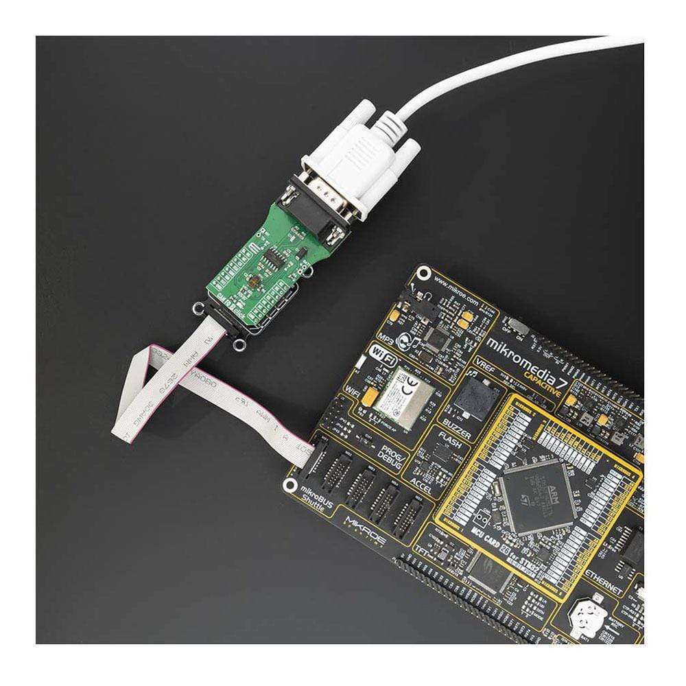
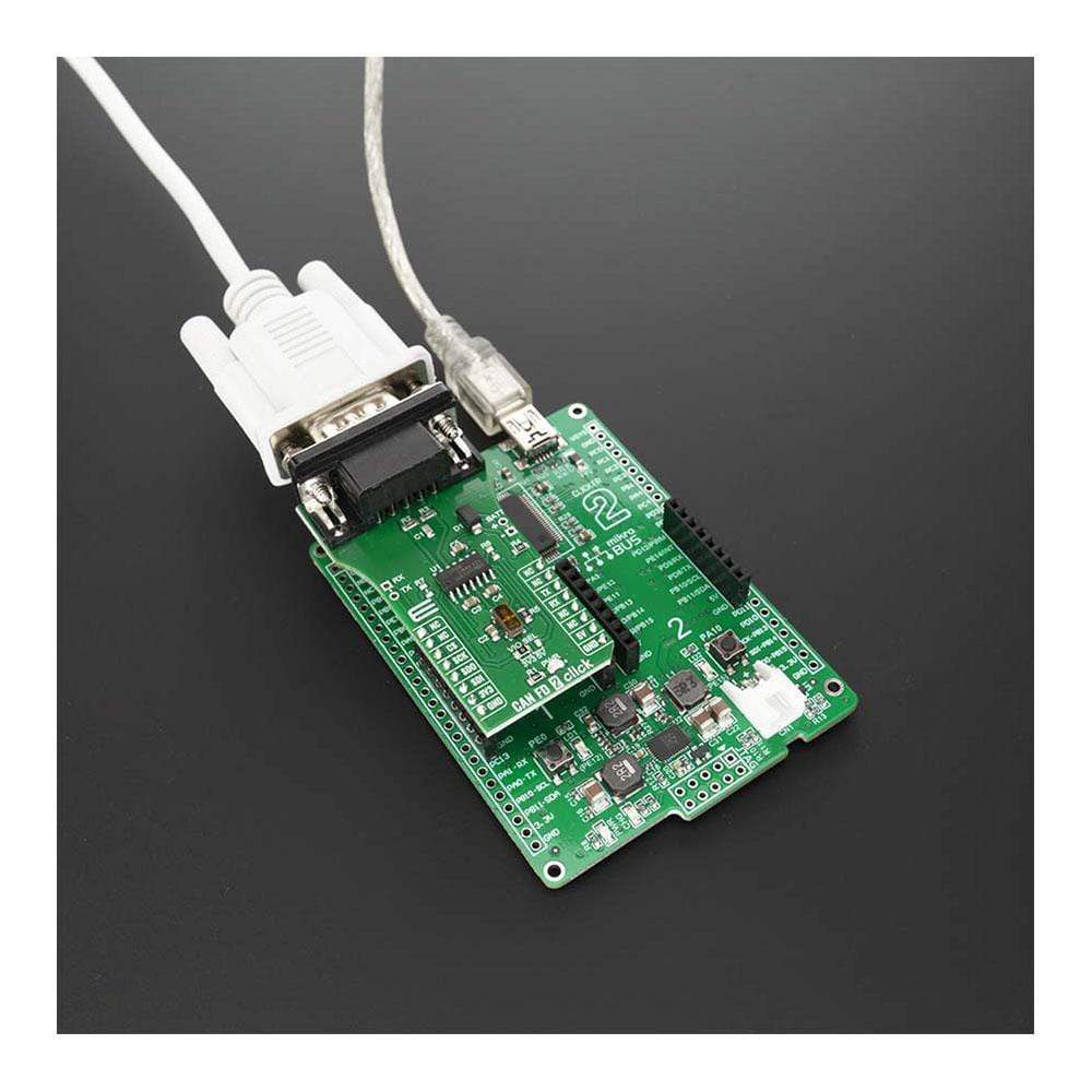
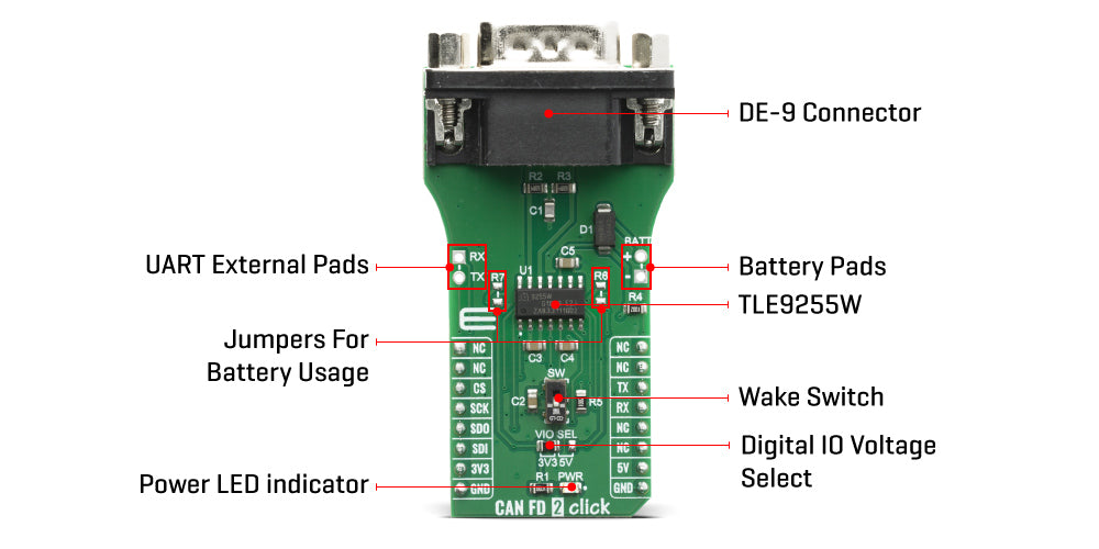
Given all the features its components offer, the CAN 2 FD Click Board™ is best used for HS CAN networks in automotive applications and HS CAN networks in industrial applications. The onboard SMD jumper labeled as the VIO SEL is used to select which voltage rail will be used as the logic voltage level. It offers voltage selection between 3.3V and 5V so that the Click board™ can be interfaced with both the 3.3V and 5V capable MCUs. The two UART wires (RX and TX) can also be connected directly through two pins to UART External Pads on the left edge of the board. With R6 and R7 jumpers populated alows you to use Click board with standard 12V battery connected on Battery Pads at right side of board.
SPECIFICATIONS
| Type | CAN,CAN FD |
| Applications | HS CAN networks in automotive applications and HS CAN networks in industrial applications |
| On-board modules | TLE9255W the HS CAN Transceiver with Partial Networking |
| Key Features | HS CAN standard data rates up to 1MBit/s, CAN FD data rates up to 5 Mbit/s, Very low electromagnetic emission, Fail safe features |
| Interface | SPI,UART |
| Compatibility | mikroBUS |
| Click board size | L (57.15 x 25.4 mm) |
| Input Voltage | 3.3V,5V |
PINOUT DIAGRAM
This table shows how the pinout for the CAN 2 FD Click Board™ corresponds to the pinout on the mikroBUS™ socket (the latter shown in the two middle columns).
| Notes | Pin | Pin | Notes | ||||
|---|---|---|---|---|---|---|---|
| NC | 1 | AN | PWM | 16 | NC | ||
| NC | 2 | RST | INT | 15 | NC | ||
| SPI Chip Select | CS | 3 | CS | RX | 14 | TX | UART Transmit |
| SPI Clock | SCK | 4 | SCK | TX | 13 | RX | UART Receive |
| SPI Data OUT | SDO | 5 | MISO | SCL | 12 | NC | |
| SPI Data IN | SDI | 6 | MOSI | SDA | 11 | NC | |
| Power Supply | 3.3V | 7 | 3.3V | 5V | 10 | 5V | Power Supply |
| Ground | GND | 8 | GND | GND | 9 | GND | Ground |
ONBOARD SETTINGS AND INDICATORS
| Label | Name | Default | Description |
|---|---|---|---|
| PWR | LED GREEN |
- | Power LED Indicator |
| SW | - | Down | Wake up switch sensitive on rising and falling edge |
| VIO SEL | - | Left | Logic voltage level selection: left position 3.3V, right position 5V |
| R6, R7 | - | NP | Jumpers for battery usage |
| General Information | |
|---|---|
Part Number (SKU) |
MIKROE-4062
|
Manufacturer |
|
| Physical and Mechanical | |
Weight |
0.02 kg
|
| Other | |
EAN |
8606018717194
|
Frequently Asked Questions
Have a Question?
Be the first to ask a question about this.